着色教程
Shadertoy Tutorial
一个大牛创作的一系列教程文章(官方网址),非常适合入门学习。可以配合着 Shadertoy 在线 GLSL ES 着色器工具一起学习。理论联系实践吗,得动手实验各种示例才有效果。另外还要参考 Inigo Quilez 这位大牛的博客,有大量关于着色方面的文章,并且他也是 shadertoy.com 的创始人之一,所以他在 Shadertoy 官网创作了大量示例程序,都是非常具有参考价值的。
这里我把这个教程复制下来了,之所以费那么大劲,原因有二:一是我非常喜欢个入门教程,示例短小精悍,简单易懂;二是鉴于某些不可说的原因,说不定这国外的网访问不了了。
教程目录
- Tutorial Part 1 - Intro
- Tutorial Part 2 - Circles and Animation
- Tutorial Part 3 - Squares and Rotation
- Tutorial Part 4 - Multiple 2D Shapes and Mixing
- Tutorial Part 5 - 2D SDF Operations and More 2D Shapes
- Tutorial Part 6 - 3D Scenes with Ray Marching
- Tutorial Part 7 - Unique Colors and Multiple 3D Objects
- Tutorial Part 8 - 3D Rotation
- Tutorial Part 9 - Camera Movement
- Tutorial Part 10 - Camera Model with a Lookat Point
- Tutorial Part 11 - Phong Reflection Model
- Tutorial Part 12 - Fresnel and Rim Lighting
- Tutorial Part 13 - Shadows
- Tutorial Part 14 - SDF Operations
- Tutorial Part 15 - Channels, Textures, and Buffers
- Tutorial Part 16 - Cubemaps and Reflections
- Snowman Shader in Shadertoy
- Shader Resources
- Glow Shader in Shadertoy
Tutorial Part 1 - Intro
转自:https://inspirnathan.com/posts/47-shadertoy-tutorial-part-1/
Greetings, friends! I’ve recently been fascinated with shaders and how amazing they are. Today, I will talk about how we can create pixel shaders using an amazing online tool called Shadertoy, created by Inigo Quilez and Pol Jeremias, two extremely talented people.
What are Shaders?
Shaders are powerful programs that were originally meant for shading objects in a 3D scene. Nowadays, shaders serve multiple purposes. Shader programs typically run on your computer’s graphics processing unit (GPU) where they can run in parallel.
TIP
Understanding that shaders run in parallel on your GPU is extremely important. Your program will independently run for every pixel in Shadertoy at the same time.
Shader languages such as the High-Level Shading Language (HLSL) and OpenGL Shading Language (GLSL) are the most common languages used to program the GPU’s rendering pipeline. These languages have syntax similar to the C programming language.
When you’re playing a game such as Minecraft, shaders are used to make the world seem 3D as you’re viewing it from a 2D screen (i.e. your computer monitor or your phone’s screen). Shaders can also drastically change the look of a game by adjusting how light interacts with objects or how objects are rendered to the screen. This YouTube video showcases 10 shaders that can make Minecraft look totally different and demonstrate the beauty of shaders.
You’ll mostly see shaders come in two forms: vertex shaders and fragment shaders. The vertex shader is used to create vertices of 3D meshes of all kinds of objects such as sphere, cubes, elephants, protagonists of a 3D game, etc. The information from the vertex shader is passed to the geometry shader which can then manipulate these vertices or perform extra operations before the fragment shader. You typically won’t hear geometry shaders being discussed much. The final part of the pipeline is the fragment shader. The fragment shader calculates the final color of the pixel and determines if a pixel should even be shown to the user or not.
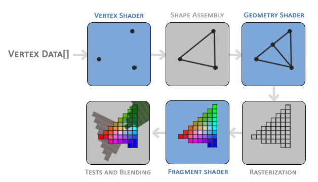
Stages of the graphics pipeline by Learn OpenGL
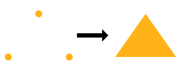
As an example, suppose we have a vertex shader that draws three points/vertices to the screen in the shape of a triangle. Once those vertices pass to the fragment shader, the pixel color between each vertex can be filled in automatically. The GPU understands how to interpolate values extremely well. Assuming a color is assigned to each vertex in the vertex shader, the GPU can interpolate colors between each vertex to fill in the triangle.
In game engines like Unity or Unreal, vertex shaders and fragment shaders are used heavily for 3D games. Unity provides an abstraction on top of shaders called ShaderLab, which is a language that sits on top of HLSL to help write shaders easier for your games. Additionally, Unity provides a visual tool called Shader Graph that lets you build shaders without writing code. If you search for “Unity shaders” on Google, you’ll find hundreds of shaders that perform lots of different functions. You can create shaders that make objects glow, make characters become translucent, and even create “image effects” that apply a shader to the entire view of your game. There are an infinite number of ways you can use shaders.
You may often hear fragment shaders be referred to as pixel shaders. The term, “fragment shader,” is more accurate because shaders can prevent pixels from being drawn to the screen. In some applications such as Shadertoy, you’re stuck drawing every pixel to the screen, so it makes more sense to call them pixel shaders in that context.
Shaders are also responsible for rendering the shading and lighting in your game, but they can be used for more than that. A shader program can run on the GPU, so why not take advantage of the parallelization it offers? You can create a compute shader that runs heavy calculations in the GPU instead of the CPU. In fact, Tensorflow.js takes advantage of the GPU to train machine learning models faster in the browser.
Shaders are powerful programs indeed!
What is Shadertoy?
In the next series of posts, I will be talking about Shadertoy. Shadertoy is a website that helps users create pixel shaders and share them with others, similar to Codepen with HTML, CSS, and JavaScript.
TIP
When following along this tutorial, please make sure you’re using a modern browser that supports WebGL 2.0 such as Google Chrome.
Shadertoy leverages the WebGL API to render graphics in the browser using the GPU. WebGL lets you write shaders in GLSL and supports hardware acceleration. That is, you can leverage the GPU to manipulate pixels on the screen in parallel to speed up rendering. Remember how you had to use ctx.getContext('2d') when working with the HTML Canvas API? Shadertoy uses a canvas with the webgl context instead of 2d, so you can draw pixels to the screen with higher performance using WebGL.
WARNING
Although Shadertoy uses the GPU to help boost rendering performance, your computer may slow down a bit when opening someone’s Shadertoy shader that performs heavy calculations. Please make sure your computer’s GPU can handle it, and understand that it may drain a device’s battery fairly quickly.
Modern 3D game engines such as Unity and the Unreal Engine and 3D modelling software such as Blender run very quickly because they use both a vertex and fragment shader, and they perform a lot of optimizations for you. In Shadertoy, you don’t have access to a vertex shader. You have to rely on algorithms such as ray marching and signed distance fields/functions (SDFs) to render 3D scenes which can be computationally expensive.
Please note that writing shaders in Shadertoy does not guarantee they will work in other environments such as Unity. You may have to translate the GLSL code to syntax supported by your target environment such as HLSL. Shadertoy also provides global variables that may not be supported in other environments. Don’t let that stop you though! It’s entirely possible to make adjustments to your Shadertoy code and use them in your games or modelling software. It just requires a bit of extra work. In fact, Shadertoy is a great way to experiment with shaders before using them in your preferred game engine or modelling software.
Shadertoy is a great way to practice creating shaders with GLSL and helps you think more mathematically. Drawing 3D scenes requires a lot of vector arithmetic. It’s intellectually stimulating and a great way to show off your skills to your friends. If you browse across Shadertoy, you’ll see tons of beautiful creations that were drawn with just math and code! Once you get the hang of Shadertoy, you’ll find it’s really fun!
Introduction to Shadertoy
Shadertoy takes care of setting up an HTML canvas with WebGL support, so all you have to worry about is writing the shader logic in the GLSL programming language. As a downside, Shadertoy doesn’t let you write vertex shaders and only lets you write pixel shaders. It essentially provides an environment for experimenting with the fragment side of shaders, so you can manipulate all pixels on the canvas in parallel.
On the top navigation bar of Shadertoy, you can click on New to start a new shader.
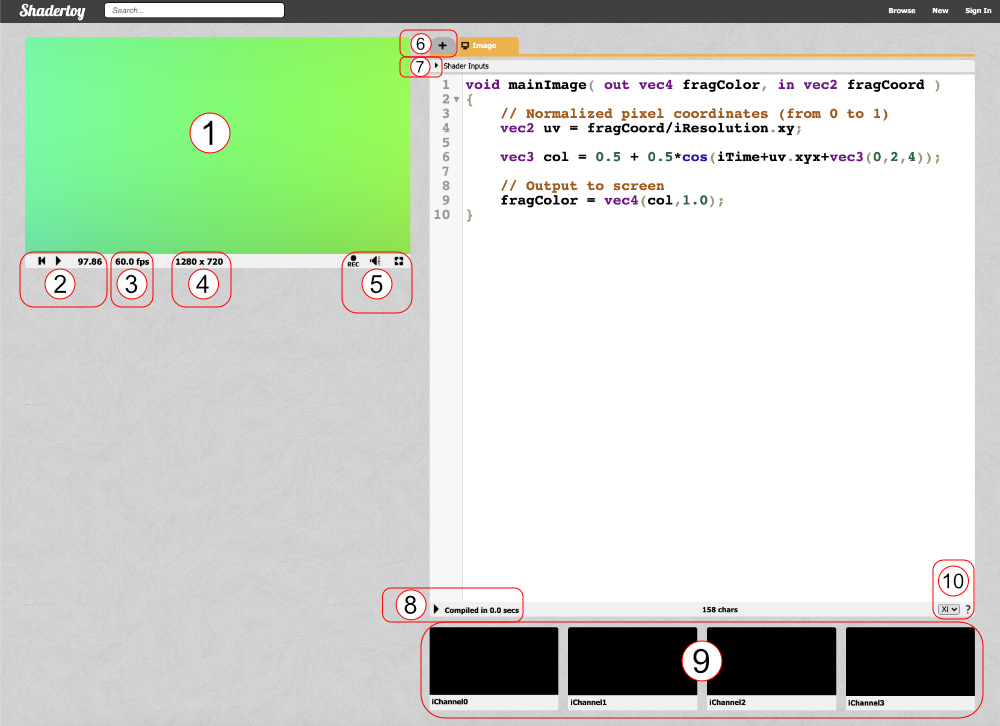
Let’s analyze everything we see on the screen. Obviously, we see a code editor on the right-hand side for writing our GLSL code, but let me go through most of the tools available as they are numbered in the image above.
- The canvas for displaying the output of your shader code. Your shader will run for every pixel in the canvas in parallel.
- Left: rewind time back to zero. Center: play/pause the shader animations. Right: Time in seconds since page loaded.
- The frames per second (fps) will let you know how well your computer can handle the shader. Typically runs around 60fps or lower.
- Canvas resolution in width by height. These values are given to you in the “iResolution” global variable.
- Left: record an html video by pressing it, recording, and pressing it again. Middle: Adjust volume for audio playing in your shader. Right: Press the symbol to expand the canvas to full screen mode.
- Click the plus icon to add additional scripts. The buffers (A, B, C, D) can be accessed using “channels” Shadertoy provides. Use “Common” to share code between scripts. Use “Sound” when you want to write a shader that generates audio. Use “Cubemap” to generate a cubemap.
- Click on the small arrow to see a list of global variables that Shadertoy provides. You can use these variables in your shader code.
- Click on the small arrow to compile your shader code and see the output in the canvas. You can use Alt+Enter or Option+Enter to quickly compile your code. You can click on the “Compiled in …” text to see the compiled code.
- Shadertoy provides four channels that can be accessed in your code through global variables such as “iChannel0”, “iChannel1”, etc. If you click on one of the channels, you can add textures or interactivity to your shader in the form of keyboard, webcam, audio, and more.
- Shadertoy gives you the option to adjust the size of your text in the code window. If you click the question mark, you can see information about the compiler being used to run your code. You can also see what functions or inputs were added by Shadertoy.
Shadertoy provides a nice environment to write GLSL code, but keep in mind that it injects variables, functions, and other utilities that may make it slightly different from GLSL code you may write in other environments. Shadertoy provides these as a convenience to you as you’re developing your shader. For example, the variable, “iTime”, is a global variable given to you to access the time (in seconds) that has passed since the page loaded.
Understanding Shader Code
When you first start a new shader in Shadertoy, you will find the following code:
 1void mainImage( out vec4 fragColor, in vec2 fragCoord )
 2{
 3  // Normalized pixel coordinates (from 0 to 1)
 4  vec2 uv = fragCoord/iResolution.xy;
 5
 6  vec3 col = 0.5 + 0.5*cos(iTime+uv.xyx+vec3(0,2,4));
 7
 8  // Output to screen
 9  fragColor = vec4(col,1.0);
10}
You can run the code by pressing the small arrow as mentioned in section 8 in the image above or you by pressing Alt+Center or Option+Enter as a keyboard shortcut.
If you’ve never worked with shaders before, that’s okay! I’ll try my best to explain the GLSL syntax you use to write shaders in Shadertoy. Right away, you will notice that this is a statically typed language like C, C++, Java, and C#. GLSL uses the concept of types too. Some of these types include: bool (boolean), int (integer), float (decimal), and vec (vector). GLSL also requires semicolons to be placed at the end of each line. Otherwise, the compiler will throw an error.
In the code snippet above, we are defining a mainImage function that must be present in our Shadertoy shader. It returns nothing, so the return type is void. It accepts two parameters: fragColor and fragCoord.
You may be scratching your head at the in and out. For Shadertoy, you generally have to worry about these keywords inside the mainImage function only. Remember how I said that the shaders allow us to write programs for the GPU rendering pipeline? Think of the in and out as the input and output. Shadertoy gives us an input, and we are writing a color as the output.
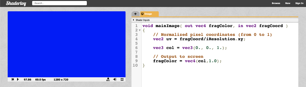
Before we continue, let’s change the code to something a bit simpler:
 1void mainImage( out vec4 fragColor, in vec2 fragCoord )
 2{
 3  // Normalized pixel coordinates (from 0 to 1)
 4  vec2 uv = fragCoord/iResolution.xy;
 5
 6  vec3 col = vec3(0., 0., 1.); // RGB values
 7
 8  // Output to screen
 9  fragColor = vec4(col,1.0);
10}
When we run the shader program, we should end up with a completely blue canvas. The shader program runs for every pixel on the canvas IN PARALLEL. This is extremely important to keep in mind. You have to think about how to write code that will change the color of the pixel depending on the pixel coordinate. It turns out we can create amazing pieces of artwork with just the pixel coordinates!
In shaders, we specify RGB (red, green, blue) values using a range between zero and one. If you have color values that are between 0 and 255, you can normalize them by dividing by 255.
So we’ve seen how to change the color of the canvas, but what’s going on inside our shader program? The first line inside the mainImage function declares a variable called uv that is of type vec2. If you remember your vector arithmetic in school, this means we have a vector with an “x” component and a “y” component. A variable with the type, vec3, would have an additional “z” component.
You may have learned in school about the 3D coordinate system. It lets us graph 3D coordinates on pieces of paper or some other flat surface. Obviously, visualizing 3D on a 2D surface is a bit difficult, so brilliant mathematicians of old created a 3D coordinate system to help us visualize points in 3D space.
However, you should think of vectors in shader code as “arrays” that can hold between one and four values. Sometimes, vectors can hold information about the XYZ coordinates in 3D space or they can contain information about RGB values. Therefore, the following are equivalent in shader programs:
color.r = color.x
color.g = color.y
color.b = color.z
color.a = color.w
Yes, there can be variables with the type, vec4, and the letter, w or a, is used to represent a fourth value. The a stands for “alpha”, since colors can have an alpha channel as well as the normal RGB values. I guess they chose w because it’s before x in the alphabet, and they already reached the last letter 🤷.
The uv variable doesn’t really represent an acronym for anything. It refers to the topic of UV Mapping that is commonly used to map pieces of a texture (such as an image) on 3D objects. The concept of UV mapping is more applicable to environments that give you access to a vertex shader unlike Shadertoy, but you can still leverage texture data in Shadertoy.
The fragCoord variable represents the XY coordinate of the canvas. The bottom-left corner starts at (0, 0) and the top-right corner is (iResolution.x, iResolution.y). By dividing fragCoord by iResolution.xy, we are able to normalize the pixel coordinates between zero and one.
Notice that we can perform arithmetic quite easily between two variables that are the same type, even if they are vectors. It’s the same as performing operations on the individual components:
1uv = fragCoord/iResolution.xy
2
3// The above is the same as:
4uv.x = fragCoord.x/iResolution.x
5uv.y = fragCoord.y/iResolution.y
When we say something like iResolution.xy, the .xy portion refers to only the XY component of the vector. This lets us strip off only the components of the vector we care about even if iResolution happens to be of type vec3.
According to this Stack Overflow post, the z-component represents the pixel aspect ratio, which is usually 1.0. A value of one means your display has square pixels. You typically won’t see people using the z-component of iResolution that often, if at all.
We can also perform shortcuts when defining vectors. The following code snippet below will set the color of the entire canvas to black.
 1void mainImage( out vec4 fragColor, in vec2 fragCoord )
 2{
 3  // Normalized pixel coordinates (from 0 to 1)
 4  vec2 uv = fragCoord/iResolution.xy;
 5
 6  vec3 col = vec3(0); // Same as vec3(0, 0, 0)
 7
 8  // Output to screen
 9  fragColor = vec4(col,1.0);
10}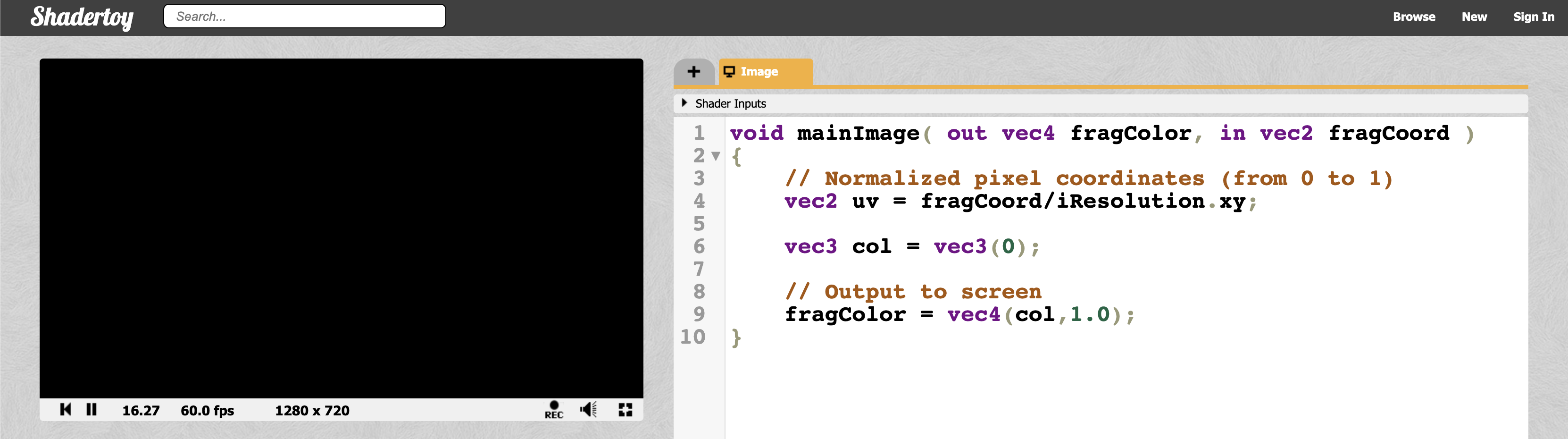
When we define a vector, the shader code is smart enough to apply the same value across all values of the vector if you only specify one value. Therefore vec3(0) gets expanded to vec3(0,0,0).
TIP
If you try to use values less than zero as the output fragment color, it will be clamped to zero. Likewise, any values greater than one will be clamped to one. This only applies to color values in the final fragment color.
It’s important to keep in mind that debugging in Shadertoy and in most shader environments, in general, is mostly visual. You don’t have anything like console.log to come to your rescue. You have to use color to help you debug.
Let’s try visualizing the pixel coordinates on the screen with the following code:
 1void mainImage( out vec4 fragColor, in vec2 fragCoord )
 2{
 3  // Normalized pixel coordinates (from 0 to 1)
 4  vec2 uv = fragCoord/iResolution.xy;
 5
 6  vec3 col = vec3(uv, 0); // This is the same as vec3(uv.x, uv.y, 0)
 7
 8  // Output to screen
 9  fragColor = vec4(col,1.0);
10}
We should end up with a canvas that is a mixture of black, red, green, and yellow.
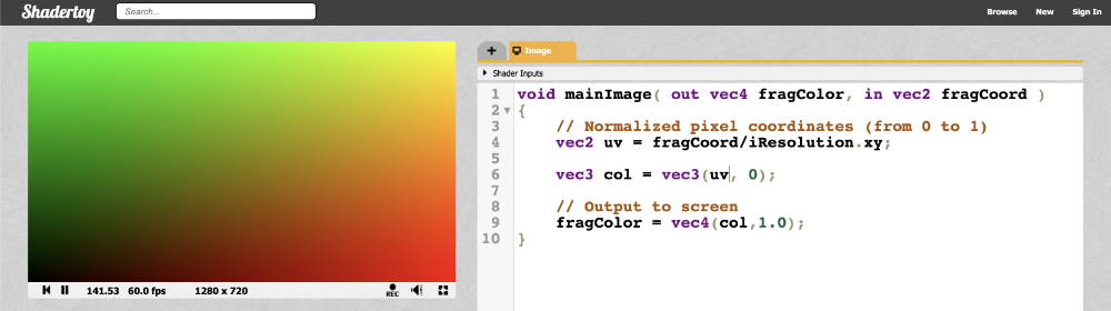
This looks pretty, but how does it help us? The uv variable represents the normalized canvas coordinates between zero and one on both the x-axis and the y-axis. The bottom-left corner of the canvas has the coordinate (0, 0). The top-right corner of the canvas has the coordinate (1, 1).
Inside the col variable, we are setting it equal to (uv.x, uv.y, 0), which means we shouldn’t expect any blue color in the canvas. When uv.x and uv.y equal zero, then we get black. When they are both equal to one, then we get yellow because in computer graphics, yellow is a combination of red and green values. The top-left corner of the canvas is (0, 1), which would mean the col variable would be equal to (0, 1, 0) which is the color green. The bottom-right corner has the coordinate of (1, 0), which means col equals (1, 0, 0) which is the color red.
Let the colors guide you in your debugging process!
Conclusion
Phew! I covered quite a lot about shaders and Shadertoy in this article. I hope you’re still with me! When I was learning shaders for the first time, it was like entering a completely new realm of programming. It’s completely different from what I’m used to, but it’s exciting and challenging! In the next series of posts, I’ll discuss how we can create shapes on the canvas and make animations!
Resources
Tutorial Part 2 - Circles and Animation
转自:https://inspirnathan.com/posts/48-shadertoy-tutorial-part-2
Greetings, friends! Today, we’ll talk about how to draw and animate a circle in a pixel shader using Shadertoy.
Practice
Before we draw our first 2D shape, let’s practice a bit more with Shadertoy. Create a new shader and replace the starting code with the following:
 1void mainImage( out vec4 fragColor, in vec2 fragCoord )
 2{
 3  vec2 uv = fragCoord/iResolution.xy; // <0,1>
 4
 5  vec3 col = vec3(0); // start with black
 6
 7  if (uv.x > .5) col = vec3(1); // make the right half of the canvas white
 8
 9  // Output to screen
10  fragColor = vec4(col,1.0);
11}
Since our shader is run in parallel across all pixels, we have to rely on if statements to draw pixels different colors depending on their location on the screen. Depending on your graphics card and the compiler being used for your shader code, it might be more performant to use built-in functions such as step.
Let’s look at the same example but use the step function instead:
 1void mainImage( out vec4 fragColor, in vec2 fragCoord )
 2{
 3  vec2 uv = fragCoord/iResolution.xy; // <0,1>
 4
 5  vec3 col = vec3(0); // start with black
 6
 7  col = vec3(step(0.5, uv.x)); // make the right half of the canvas white
 8
 9  // Output to screen
10  fragColor = vec4(col,1.0);
11}
The left half of the canvas will be black and the right half of the canvas will be white.

The step function accepts two inputs: the edge of the step function, and a value used to generate the step function. If the second parameter in the function argument is greater than the first, then return a value of one. Otherwise, return a value of zero.
You can perform the step function across each component in a vector as well:
 1void mainImage( out vec4 fragColor, in vec2 fragCoord )
 2{
 3  vec2 uv = fragCoord/iResolution.xy; // <0,1>
 4
 5  vec3 col = vec3(0); // start with black
 6
 7  col = vec3(step(0.5, uv), 0); // perform step function across the x-component and y-component of uv
 8
 9  // Output to screen
10  fragColor = vec4(col,1.0);
11}
Since the step function operates on both the X component and Y component of the canvas, you should see the canvas get split into four colors.

How to Draw Circles
The equation of a circle is defined by the following:
x^2 + y^2 = r^2

x = x-coordinate on graph
y = y-coordinate on graph
r = radius of circle
We can re-arrange the variables to make the equation equal to zero:
x^2 + y^2 - r^2 = 0To visualize this on a graph, you can use the Desmos calculator to graph the following:
x^2 + y^2 - 4 = 0If you copy the above snippet and paste it into the Desmos calculator, then you should see a graph of a circle with a radius of two. The center of the circle is located at the coordinate, (0, 0).

In Shadertoy, we can use the left-hand side (LHS) of this equation to make a circle. Let’s create a function called sdfCircle that returns the color, white, for each pixel at an XY-coordinate such that the equation is greater than zero and the color, blue, otherwise.
The sdf part of the function refers to a concept called signed distance functions (SDF), aka signed distance fields. It’s more common to use SDFs when drawing in 3D, but I will use this term for 2D shapes as well.
We will call our new function in the mainImage function to use it.
 1vec3 sdfCircle(vec2 uv, float r) {
 2    float x = uv.x;
 3    float y = uv.y;
 4
 5    float d = length(vec2(x, y)) - r;
 6
 7    return d > 0. ? vec3(1.) : vec3(0., 0., 1.);
 8}
 9
10void mainImage( out vec4 fragColor, in vec2 fragCoord )
11{
12  vec2 uv = fragCoord/iResolution.xy; // <0,1>
13
14  vec3 col = sdfCircle(uv, .2); // Call this function on each pixel to check if the coordinate lies inside or outside of the circle
15
16  // Output to screen
17  fragColor = vec4(col,1.0);
18}
If you’re wondering why I use 0. instead of simply 0 without a decimal, it’s because adding a decimal at the end of an integer will make it make it have a type of float instead of int. When you’re using functions that require numbers that are of type float, placing a decimal at the end of an integer is the easiest way to satisfy the compiler.
We’re using a radius of 0.2 because our coordinate system is set up to only have UV values that are between zero and one. When you run the code, you’ll notice that something appears wrong.

There seems to be a quarter of a blue dot in the bottom-left corner of the canvas. Why? Because our coordinate system is currently setup such that the origin is at the bottom-left corner. We need to shift every value by 0.5 to get the origin of the coordinate system at the center of the canvas.
Subtract 0.5 from the UV coordinates:
1vec2 uv = fragCoord/iResolution.xy; // <0,1>
2uv -= 0.5; // <-0.5, 0.5>
Now the range is between -0.5 and 0.5 on both the x-axis and y-axis, which means the origin of the coordinate system is in the center of the canvas. However, we face another issue…

Our circle appears a bit stretched, so it looks more like an ellipse. This is caused by the aspect ratio of the canvas. When the width and the height of the canvas don’t match, the circle appears stretched. We can fix this issue by multiplying the X component of the UV coordinates by the aspect ratio of the canvas.
1vec2 uv = fragCoord/iResolution.xy; // <0,1>
2uv -= 0.5; // <-0.5, 0.5>
3uv.x *= iResolution.x/iResolution.y; // fix aspect ratio
This means the X component no longer goes between -0.5 and 0.5. It will go between values proportional to the aspect ratio of your canvas which will be determined by the width of your browser or webpage (if you’re using something like Chrome DevTools to alter the width).
Your finished code should look like the following:
 1vec3 sdfCircle(vec2 uv, float r) {
 2  float x = uv.x;
 3  float y = uv.y;
 4
 5  float d = length(vec2(x, y)) - r;
 6
 7  return d > 0. ? vec3(1.) : vec3(0., 0., 1.);
 8}
 9
10void mainImage( out vec4 fragColor, in vec2 fragCoord )
11{
12  vec2 uv = fragCoord/iResolution.xy; // <0,1>
13  uv -= 0.5;
14  uv.x *= iResolution.x/iResolution.y; // fix aspect ratio
15
16  vec3 col = sdfCircle(uv, .2);
17
18  // Output to screen
19  fragColor = vec4(col,1.0);
20}
Once you run the code, you should see a perfectly proportional blue circle! 🎉
TIP
Please note that this is simply one way of coloring a circle. We will learn an alternative approach in Part 4 of this tutorial series. It will help us draw multiple shapes to the canvas.

We can have some fun with this! We can use the global iTime variable to change colors over time. By using a cosine (cos) function, we can cycle through the same set of colors over and over. Since cosine functions oscillate between the values -1 and 1, we need to adjust this range to values between zero and one.
Remember, any color values in the final fragment color that are less than zero will automatically be clamped to zero. Likewise, any color values greater than one will be clamped to one. By adjusting the range, we get a wider range of colors.
 1vec3 sdfCircle(vec2 uv, float r) {
 2  float x = uv.x;
 3  float y = uv.y;
 4
 5  float d = length(vec2(x, y)) - r;
 6
 7  return d > 0. ? vec3(0.) : 0.5 + 0.5 * cos(iTime + uv.xyx + vec3(0,2,4));
 8}
 9
10void mainImage( out vec4 fragColor, in vec2 fragCoord )
11{
12  vec2 uv = fragCoord/iResolution.xy; // <0,1>
13  uv -= 0.5;
14  uv.x *= iResolution.x/iResolution.y; // fix aspect ratio
15
16  vec3 col = sdfCircle(uv, .2);
17
18  // Output to screen
19  fragColor = vec4(col,1.0);
20}
Once you run the code, you should see the circle change between various colors.

You might be confused by the syntax in uv.xyx. This is called Swizzling. We can create new vectors using components of a variable. Let’s look at an example.
1vec3 col = vec3(0.2, 0.4, 0.6);
2vec3 col2 = col.xyx;
3vec3 col3 = vec3(0.2, 0.4, 0.2);
In the code snippet above, col2 and col3 are identical.
Moving the Circle
To move the circle, we need to apply an offset to the XY coordinates inside the equation for a circle. Therefore, our equation will look like the following:
1(x - offsetX)^2 + (y - offsetY)^2 - r^2 = 0
2
3x = x-coordinate on graph
4y = y-coordinate on graph
5r = radius of circle
6offsetX = how much to move the center of the circle in the x-axis
7offsetY = how much to move the center of the circle in the y-axis
You can experiment in the Desmos calculator again by copying and pasting the following code:
(x - 2)^2 + (y - 2)^2 - 4 = 0
Inside Shadertoy, we can adjust our sdfCircle function to allow offsets and then move the center of the circle by 0.2.
 1vec3 sdfCircle(vec2 uv, float r, vec2 offset) {
 2  float x = uv.x - offset.x;
 3  float y = uv.y - offset.y;
 4
 5  float d = length(vec2(x, y)) - r;
 6
 7  return d > 0. ? vec3(1.) : vec3(0., 0., 1.);
 8}
 9
10void mainImage( out vec4 fragColor, in vec2 fragCoord )
11{
12  vec2 uv = fragCoord/iResolution.xy; // <0,1>
13  uv -= 0.5;
14  uv.x *= iResolution.x/iResolution.y; // fix aspect ratio
15
16  vec2 offset = vec2(0.2, 0.2); // move the circle 0.2 units to the right and 0.2 units up
17
18  vec3 col = sdfCircle(uv, .2, offset);
19
20  // Output to screen
21  fragColor = vec4(col,1.0);
22}
You can again use the global iTime variable in certain places to give life to your canvas and animate your circle.
 1vec3 sdfCircle(vec2 uv, float r, vec2 offset) {
 2  float x = uv.x - offset.x;
 3  float y = uv.y - offset.y;
 4
 5  float d = length(vec2(x, y)) - r;
 6
 7  return d > 0. ? vec3(1.) : vec3(0., 0., 1.);
 8}
 9
10void mainImage( out vec4 fragColor, in vec2 fragCoord )
11{
12  vec2 uv = fragCoord/iResolution.xy; // <0,1>
13  uv -= 0.5;
14  uv.x *= iResolution.x/iResolution.y; // fix aspect ratio
15
16  vec2 offset = vec2(sin(iTime*2.)*0.2, cos(iTime*2.)*0.2); // move the circle clockwise
17
18  vec3 col = sdfCircle(uv, .2, offset);
19
20  // Output to screen
21  fragColor = vec4(col,1.0);
22}
The above code will move the circle along a circular path in the clockwise direction as if it’s rotating about the origin. By multiplying iTime by a value, you can speed up the animation. By multiplying the output of the sine or cosine function by a value, you can control how far the circle moves from the center of the canvas. You’ll use sine and cosine functions a lot with iTime because they create oscillation.

Conclusion
In this lesson, we learned how to fix the coordinate system of the canvas, draw a circle, and animate the circle along a circular path. Circles, circles, circles! 🔵
In the next lesson, I’ll show you how to draw a square to the screen. Then, we’ll learn how to rotate it!
Tutorial Part 3 - Squares and Rotation
转自:https://inspirnathan.com/posts/49-shadertoy-tutorial-part-3
Greetings, friends! In the previous article, we learned how to draw circles and animate them. In this tutorial, we will learn how to draw squares and rotate them using a rotation matrix.
How to Draw Squares
Drawing a square is very similar to drawing a circle except we will use a different equation. In fact, you can draw practically any 2D shape you want if you have an equation for it!
The equation of a square is defined by the following:
max(abs(x),abs(y)) = r

x = x-coordinate on graph
y = y-coordinate on graph
r = radius of square
We can re-arrange the variables to make the equation equal to zero:
max(abs(x), abs(y)) - r = 0To visualize this on a graph, you can use the Desmos calculator to graph the following:
max(abs(x), abs(y)) - 2 = 0If you copy the above snippet and paste it into the Desmos calculator, then you should see a graph of a square with a radius of two. The center of the square is located at the origin, (0, 0).

You can also include an offset:
max(abs(x - offsetX), abs(y - offsetY)) - r = 0

offsetX = how much to move the center of the square in the x-axis
offsetY = how much to move the center of the square in the y-axis
The steps for drawing a square using a pixel shader is very similar to the previous tutorial where we created a circle. Instead, we’ll be creating a function specifically for a square.
 1vec3 sdfSquare(vec2 uv, float size, vec2 offset) {
 2  float x = uv.x - offset.x;
 3  float y = uv.y - offset.y;
 4  float d = max(abs(x), abs(y)) - size;
 5
 6  return d > 0. ? vec3(1.) : vec3(1., 0., 0.);
 7}
 8
 9
10void mainImage( out vec4 fragColor, in vec2 fragCoord )
11{
12  vec2 uv = fragCoord/iResolution.xy; // <0, 1>
13  uv -= 0.5; // <-0.5,0.5>
14  uv.x *= iResolution.x/iResolution.y; // fix aspect ratio
15
16  vec2 offset = vec2(0.0, 0.0);
17
18  vec3 col = sdfSquare(uv, 0.2, offset);
19
20  // Output to screen
21  fragColor = vec4(col,1.0);
22}
Yay! Now we have a red square! 🟥

Rotating shapes
You can rotate shapes by using a rotation matrix given by the following notation:
$$ R=\begin{bmatrix}\cos\theta&-\sin\theta\\sin\theta&\cos\theta\end{bmatrix} $$ Matrices can help us work with multiple linear equations and linear transformations. In fact, a rotational matrix is a type of transformation matrix. We can use matrices to perform other transformations such as shearing, translation, or reflection.
TIP
If you want to play around with matrix arithmetic, you can use either the Demos Matrix Calculator or WolframAlpha. If you need a refresher on matrices, you can watch this amazing video by Derek Banas on YouTube.
We can use a graph I created on Desmos to help visualize rotations. I have created a set of parametric equations that use the rotation matrix in its linear equation form.

The linear equation form is obtained by multiplying the rotation matrix by the vector [x,y] as calculated by WolframAlpha. The result is an equation for the transformed x-coordinate and transformed y-coordinate after the rotation.
In Shadertoy, we only care about the rotation matrix, not the linear equation form. I only discuss the linear equation form for the purpose of showing rotations in Desmos.
We can create a rotate function in our shader code that accepts UV coordinates and an angle by which to rotate the square. It will return the rotation matrix multiplied by the UV coordinates. Then, we’ll call the rotate function inside the sdfSquare function by passing in our XY coordinates, shifted by an offset (if it exists). We will use iTime as the angle, so that the square animates.
 1vec2 rotate(vec2 uv, float th) {
 2  return mat2(cos(th), sin(th), -sin(th), cos(th)) * uv;
 3}
 4
 5vec3 sdfSquare(vec2 uv, float size, vec2 offset) {
 6  float x = uv.x - offset.x;
 7  float y = uv.y - offset.y;
 8  vec2 rotated = rotate(vec2(x,y), iTime);
 9  float d = max(abs(rotated.x), abs(rotated.y)) - size;
10
11  return d > 0. ? vec3(1.) : vec3(1., 0., 0.);
12}
13
14void mainImage( out vec4 fragColor, in vec2 fragCoord )
15{
16  vec2 uv = fragCoord/iResolution.xy; // <0, 1>
17  uv -= 0.5; // <-0.5,0.5>
18  uv.x *= iResolution.x/iResolution.y; // fix aspect ratio
19
20  vec2 offset = vec2(0.0, 0.0);
21
22  vec3 col = sdfSquare(uv, 0.2, offset);
23
24  // Output to screen
25  fragColor = vec4(col,1.0);
26}
Notice how we defined the matrix in Shadertoy. Let’s inspect the rotate function more closely.
1vec2 rotate(vec2 uv, float th) {
2  return mat2(cos(th), sin(th), -sin(th), cos(th)) * uv;
3}
According to this wiki on GLSL, we define a matrix by comma-separated values, but we go through the matrix column-first. Since this is a matrix of type mat2, it is a 2x2 matrix. The first two values represent the first column, and the last two values represent the second-column. In tools such as WolframAlpha, you insert values row-first instead and use square brackets to separate each row. Keep this in mind as you’re experimenting with matrices.
Our rotate function returns a value that is of type vec2 because a 2x2 matrix (mat2) multiplied by a vec2 vector returns another vec2 vector.
When we run the code, we should see the square rotate in the clockwise direction.

Conclusion
In this lesson, we learned how to draw a square and rotate it using a transformation matrix. Using the knowledge you have gained from this tutorial and the previous one, you can draw any 2D shape you want using an equation or SDF for that shape!
In the next article, I’ll discuss how to draw multiple shapes on the canvas while being able to change the background color as well.
Resources
- 2D Rotation Example
- Vector and Matrix Operations in GLSL
- Vector and Matrix Transformations
- Matrix Arithmetic
- 2D SDFs
Tutorial Part 4 - Multiple 2D Shapes and Mixing
转自:https://inspirnathan.com/posts/50-shadertoy-tutorial-part-4
UPDATE
This article has been revamped as of May 3, 2021. I replaced most of the code snippets with a cleaner solution for drawing 2D shapes.
Greetings, friends! In the past couple tutorials, we’ve learned how to draw 2D shapes to the canvas using Shadertoy. In this article, I’d like to discuss a better approach to drawing 2D shapes, so we can easily add multiple shapes to the canvas. We’ll also learn how to change the background color independent from the shape colors.
The Mix Function
Before we continue, let’s take a look at the mix function. This function will be especially useful to us as we render multiple 2D shapes to the scene.
The mix function linearly interpolates between two values. In other shader languages such as HLSL, this function is known as lerp instead.
Linear interpolation for the function, mix(x, y, a), is based on the following formula:
x * (1 - a) + y * a

x = first value
y = second value
a = value that linearly interpolates between x and y
Think of the third parameter, a, as a slider that lets you choose values between x and y.
You will see the mix function used heavily in shaders. It’s a great way to create color gradients. Let’s look at an example:
 1void mainImage( out vec4 fragColor, in vec2 fragCoord )
 2{
 3    vec2 uv = fragCoord/iResolution.xy; // <0, 1>
 4
 5    float interpolatedValue = mix(0., 1., uv.x);
 6    vec3 col = vec3(interpolatedValue);
 7
 8    // Output to screen
 9    fragColor = vec4(col,1.0);
10}
In the above code, we are using the mix function to get an interpolated value per pixel on the screen across the x-axis. By using the same value across the red, green, and blue channels, we get a gradient that goes from black to white, with shades of gray in between.

We can also use the mix function along the y-axis:
1float interpolatedValue = mix(0., 1., uv.y);
Using this knowledge, we can create a colored gradient in our pixel shader. Let’s define a function specifically for setting the background color of the canvas.
 1vec3 getBackgroundColor(vec2 uv) {
 2    uv += 0.5; // remap uv from <-0.5,0.5> to <0,1>
 3    vec3 gradientStartColor = vec3(1., 0., 1.);
 4    vec3 gradientEndColor = vec3(0., 1., 1.);
 5    return mix(gradientStartColor, gradientEndColor, uv.y); // gradient goes from bottom to top
 6}
 7
 8void mainImage( out vec4 fragColor, in vec2 fragCoord )
 9{
10    vec2 uv = fragCoord/iResolution.xy; // <0, 1>
11    uv -= 0.5; // <-0.5,0.5>
12    uv.x *= iResolution.x/iResolution.y; // fix aspect ratio
13
14    vec3 col = getBackgroundColor(uv);
15
16    // Output to screen
17    fragColor = vec4(col,1.0);
18}
This will produce a cool gradient that goes between shades of purple and cyan.

When using the mix function on vectors, it will use the third parameter to interpolate each vector on a component basis. It will run through the interpolator function for the red component (or x-component) of the gradientStartColor vector and the red component of the gradientEndColor vector. The same tactic will be applied to the green (y-component) and blue (z-component) channels of each vector.
We added 0.5 to the value of uv because in most situations, we will be working with values of uv that range between a negative number and positive number. If we pass a negative value into the final fragColor, then it’ll be clamped to zero. We shift the range away from negative values for the purpose of displaying color in the full range.
An Alternative Way to Draw 2D Shapes
In the previous tutorials, we learned how to use 2D SDFs to create 2D shapes such as circles and squares. However, the sdfCircle and sdfSquare functions were returning a color in the form of a vec3 vector.
Typically, SDFs return a float and not vec3 value. Remember, “SDF” is an acronym for “signed distance fields.” Therefore, we expect them to return a distance of type float. In 3D SDFs, this is usually true, but in 2D SDFs, I find it’s more useful to return either a one or zero depending on whether the pixel is inside the shape or outside the shape as we’ll see later.
The distance is relative to some point, typically the center of the shape. If a circle’s center is at the origin, (0, 0), then we know that any point on the edge of the circle is equal to the radius of the circle, hence the equation:
x^2 + y^2 = r^2

Or, when rearranged,
x^2 + y^2 - r^2 = 0

where x^2 + y^2 - r^2 = distance = d
If the distance is greater than zero, then we know that we are outside the circle. If the distance is less than zero, then we are inside the circle. If the distance is equal to zero exactly, then we’re on the edge of the circle. This is where the “signed” part of the “signed distance field” comes into play. The distance can be negative or positive depending on whether the pixel coordinate is inside or outside the shape.
In Part 2 of this tutorial series, we drew a blue circle using the following code:
 1vec3 sdfCircle(vec2 uv, float r) {
 2  float x = uv.x;
 3  float y = uv.y;
 4
 5  float d = length(vec2(x, y)) - r;
 6
 7  return d > 0. ? vec3(1.) : vec3(0., 0., 1.);
 8  // draw background color if outside the shape
 9  // draw circle color if inside the shape
10}
11
12void mainImage( out vec4 fragColor, in vec2 fragCoord )
13{
14  vec2 uv = fragCoord/iResolution.xy; // <0,1>
15  uv -= 0.5;
16  uv.x *= iResolution.x/iResolution.y; // fix aspect ratio
17
18  vec3 col = sdfCircle(uv, .2);
19
20  // Output to screen
21  fragColor = vec4(col,1.0);
22}
The problem with this approach is that we’re forced to draw a circle with the color, blue, and a background with the color, white.
We need to make the code a bit more abstract, so we can draw the background and shape colors independent of each other. This will allow us to draw multiple shapes to the scene and select any color we want for each shape and the background.
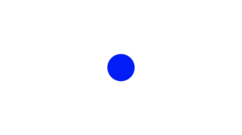
Let’s look at an alternative way of drawing the blue circle:
 1float sdfCircle(vec2 uv, float r, vec2 offset) {
 2  float x = uv.x - offset.x;
 3  float y = uv.y - offset.y;
 4
 5  return length(vec2(x, y)) - r;
 6}
 7
 8vec3 drawScene(vec2 uv) {
 9  vec3 col = vec3(1);
10  float circle = sdfCircle(uv, 0.1, vec2(0, 0));
11
12  col = mix(vec3(0, 0, 1), col, step(0., circle));
13
14  return col;
15}
16
17void mainImage( out vec4 fragColor, in vec2 fragCoord )
18{
19  vec2 uv = fragCoord/iResolution.xy; // <0, 1>
20  uv -= 0.5; // <-0.5,0.5>
21  uv.x *= iResolution.x/iResolution.y; // fix aspect ratio
22
23  vec3 col = drawScene(uv);
24
25  // Output to screen
26  fragColor = vec4(col,1.0);
27}
In the code above, we are now abstracting out a few things. We have a drawScene function that will be responsible for rendering the scene, and the sdfCircle now returns a float that represents the “signed distance” between a pixel on the screen and a point on the circle.
We learned about the step function in Part 2. It returns a value of one or zero depending on the value of the second parameter. In fact, the following are equivalent:
1float result = step(0., circle);
2float result = circle > 0. ? 1. : 0.;
If the “signed distance” value is greater than zero, then that means, the point is inside the circle. If the value is less than or equal to zero, then the point is outside or on the edge of the circle.
Inside the drawScene function, we are using the mix function to blend the white background color with the color, blue. The value of circle will determine if the pixel is white (the background) or blue (the circle). In this sense, we can use the mix function as a “toggle” that will switch between the shape color or background color depending on the value of the third parameter.
Using an SDF in this way basically lets us draw the shape only if the pixel is at a coordinate that lies within the shape. Otherwise, it should draw the color that was there before.
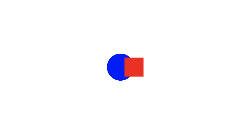
Let’s add a square that is offset from the center a bit.
 1float sdfCircle(vec2 uv, float r, vec2 offset) {
 2  float x = uv.x - offset.x;
 3  float y = uv.y - offset.y;
 4
 5  return length(vec2(x, y)) - r;
 6}
 7
 8float sdfSquare(vec2 uv, float size, vec2 offset) {
 9  float x = uv.x - offset.x;
10  float y = uv.y - offset.y;
11
12  return max(abs(x), abs(y)) - size;
13}
14
15vec3 drawScene(vec2 uv) {
16  vec3 col = vec3(1);
17  float circle = sdfCircle(uv, 0.1, vec2(0, 0));
18  float square = sdfSquare(uv, 0.07, vec2(0.1, 0));
19
20  col = mix(vec3(0, 0, 1), col, step(0., circle));
21  col = mix(vec3(1, 0, 0), col, step(0., square));
22
23  return col;
24}
25
26void mainImage( out vec4 fragColor, in vec2 fragCoord )
27{
28  vec2 uv = fragCoord/iResolution.xy; // <0, 1>
29  uv -= 0.5; // <-0.5,0.5>
30  uv.x *= iResolution.x/iResolution.y; // fix aspect ratio
31
32  vec3 col = drawScene(uv);
33
34  // Output to screen
35  fragColor = vec4(col,1.0);
36}
Using the mix function with this approach lets us easily render multiple 2D shapes to the scene!
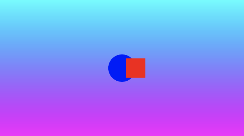
Custom Background and Multiple 2D Shapes
With the knowledge we’ve learned, we can easily customize our background while leaving the color of our shapes intact. Let’s add a function that returns a gradient color for the background and use it at the top of the drawScene function.
1vec3 getBackgroundColor(vec2 uv) {
2 uv += 0.5; // remap uv from <-0.5,0.5> to <0,1>
3 vec3 gradientStartColor = vec3(1., 0., 1.);
4 vec3 gradientEndColor = vec3(0., 1., 1.);
5 return mix(gradientStartColor, gradientEndColor, uv.y); // gradient goes from bottom to top
6}
7
8float sdfCircle(vec2 uv, float r, vec2 offset) {
9 float x = uv.x - offset.x;
10 float y = uv.y - offset.y;
11
12 return length(vec2(x, y)) - r;
13}
14
15float sdfSquare(vec2 uv, float size, vec2 offset) {
16 float x = uv.x - offset.x;
17 float y = uv.y - offset.y;
18 return max(abs(x), abs(y)) - size;
19}
20
21vec3 drawScene(vec2 uv) {
22 vec3 col = getBackgroundColor(uv);
23 float circle = sdfCircle(uv, 0.1, vec2(0, 0));
24 float square = sdfSquare(uv, 0.07, vec2(0.1, 0));
25
26 col = mix(vec3(0, 0, 1), col, step(0., circle));
27 col = mix(vec3(1, 0, 0), col, step(0., square));
28
29 return col;
30}
31
32void mainImage( out vec4 fragColor, in vec2 fragCoord )
33{
34 vec2 uv = fragCoord/iResolution.xy; // <0, 1>
35 uv -= 0.5; // <-0.5,0.5>
36 uv.x *= iResolution.x/iResolution.y; // fix aspect ratio
37
38 vec3 col = drawScene(uv);
39
40 // Output to screen
41 fragColor = vec4(col,1.0);
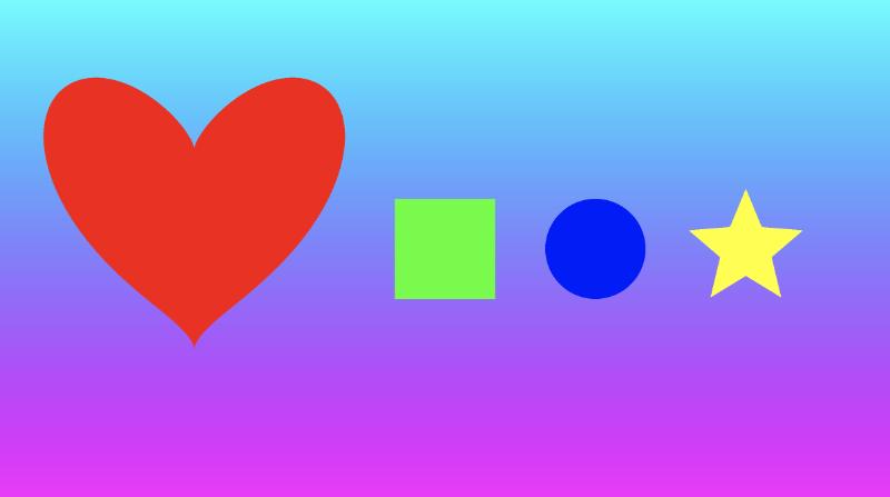
42}Simply stunning! 🤩
Would this piece of abstract digital art make a lot of money as a non-fungible token 🤔. Probably not, but one can hope 😅.
Conclusion
In this lesson, we created a beautiful piece of digital art. We learned how to use the mix function to create a color gradient and how to use it to render shapes on top of each other or on top of a background layer. In the next lesson, I’ll talk about other 2D shapes we can draw such as hearts and stars.
Resources
Tutorial Part 5 - 2D SDF Operations and More 2D Shapes
转自:https://inspirnathan.com/posts/51-shadertoy-tutorial-part-5
UPDATE
This article has been heavily revamped as of May 3, 2021. I added a new section on 2D SDF operations, replaced all the code snippets with a cleaner solution for drawing 2D shapes, and added a section on Quadratic Bézier curves. Enjoy!
Greetings, friends! In this tutorial, I’ll discuss how to use 2D SDF operations to create more complex shapes from primitive shapes, and I’ll discuss how to draw more primitive 2D shapes, including hearts and stars. I’ll help you utilize this list of 2D SDFs that was popularized by the talented Inigo Quilez, one of the co-creators of Shadertoy. Let’s begin!
Combination 2D SDF Operations
In the previous tutorials, we’ve seen how to draw primitive 2D shapes such as circles and squares, but we can use 2D SDF operations to create more complex shapes by combining primitive shapes together.
Let’s start with some simple boilerplate code for 2D shapes:
 1vec3 getBackgroundColor(vec2 uv) {
 2  uv = uv * 0.5 + 0.5; // remap uv from <-0.5,0.5> to <0.25,0.75>
 3  vec3 gradientStartColor = vec3(1., 0., 1.);
 4  vec3 gradientEndColor = vec3(0., 1., 1.);
 5  return mix(gradientStartColor, gradientEndColor, uv.y); // gradient goes from bottom to top
 6}
 7
 8float sdCircle(vec2 uv, float r, vec2 offset) {
 9  float x = uv.x - offset.x;
10  float y = uv.y - offset.y;
11
12  return length(vec2(x, y)) - r;
13}
14
15float sdSquare(vec2 uv, float size, vec2 offset) {
16  float x = uv.x - offset.x;
17  float y = uv.y - offset.y;
18
19  return max(abs(x), abs(y)) - size;
20}
21
22vec3 drawScene(vec2 uv) {
23  vec3 col = getBackgroundColor(uv);
24  float d1 = sdCircle(uv, 0.1, vec2(0., 0.));
25  float d2 = sdSquare(uv, 0.1, vec2(0.1, 0));
26
27  float res; // result
28  res = d1;
29
30  res = step(0., res); // Same as res > 0. ? 1. : 0.;
31
32  col = mix(vec3(1,0,0), col, res);
33  return col;
34}
35
36void mainImage( out vec4 fragColor, in vec2 fragCoord )
37{
38  vec2 uv = fragCoord/iResolution.xy; // <0, 1>
39  uv -= 0.5; // <-0.5,0.5>
40  uv.x *= iResolution.x/iResolution.y; // fix aspect ratio
41
42  vec3 col = drawScene(uv);
43
44  fragColor = vec4(col,1.0); // Output to screen
45}
Please note how I’m now using sdCircle for the function name instead of sdfCircle (which was used in previous tutorials). Inigo Quilez’s website commonly uses sd in front of the shape name, but I was using sdf to help make it clear that these are signed distance fields (SDF).
When you run the code, you should see a red circle with a gradient background color, similar to what we learned in the previous tutorial.
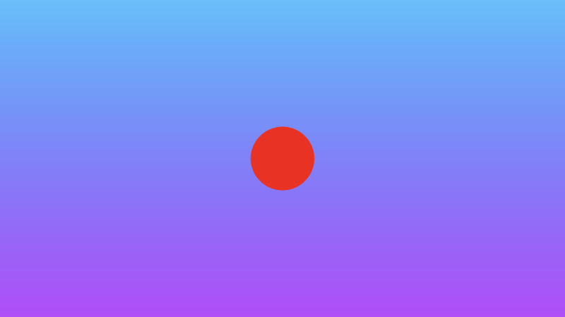
Pay attention to where we use the mix function:
1col = mix(vec3(1,0,0), col, res);This line says to take the result and either pick the color red or the value of col (currently the background color) depending on the value of res (the result).
Now, let’s discuss the various SDF operations that can be performed. We will look at the interaction between a circle and a square.
Union: combine two shapes together.
 1vec3 drawScene(vec2 uv) {
 2  vec3 col = getBackgroundColor(uv);
 3  float d1 = sdCircle(uv, 0.1, vec2(0., 0.));
 4  float d2 = sdSquare(uv, 0.1, vec2(0.1, 0));
 5
 6  float res; // result
 7  res = min(d1, d2); // union
 8
 9  res = step(0., res); // Same as res > 0. ? 1. : 0.;
10
11  col = mix(vec3(1,0,0), col, res);
12  return col;
13}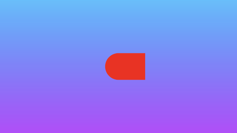
Intersection: take only the part where the two shapes intersect.
 1vec3 drawScene(vec2 uv) {
 2  vec3 col = getBackgroundColor(uv);
 3  float d1 = sdCircle(uv, 0.1, vec2(0., 0.));
 4  float d2 = sdSquare(uv, 0.1, vec2(0.1, 0));
 5
 6  float res; // result
 7  res = max(d1, d2); // intersection
 8
 9  res = step(0., res); // Same as res > 0. ? 1. : 0.;
10
11  col = mix(vec3(1,0,0), col, res);
12  return col;
13}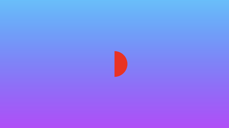
Subtraction: subtract d1 from d2.
 1vec3 drawScene(vec2 uv) {
 2  vec3 col = getBackgroundColor(uv);
 3  float d1 = sdCircle(uv, 0.1, vec2(0., 0.));
 4  float d2 = sdSquare(uv, 0.1, vec2(0.1, 0));
 5
 6  float res; // result
 7  res = max(-d1, d2); // subtraction - subtract d1 from d2
 8
 9  res = step(0., res); // Same as res > 0. ? 1. : 0.;
10
11  col = mix(vec3(1,0,0), col, res);
12  return col;
13}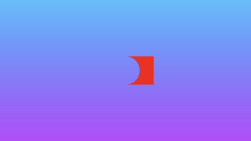
Subtraction: subtract d2 from d1.
 1vec3 drawScene(vec2 uv) {
 2  vec3 col = getBackgroundColor(uv);
 3  float d1 = sdCircle(uv, 0.1, vec2(0., 0.));
 4  float d2 = sdSquare(uv, 0.1, vec2(0.1, 0));
 5
 6  float res; // result
 7  res = max(d1, -d2); // subtraction - subtract d2 from d1
 8
 9  res = step(0., res); // Same as res > 0. ? 1. : 0.;
10
11  col = mix(vec3(1,0,0), col, res);
12  return col;
13}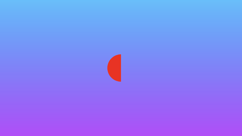
XOR: an exclusive “OR” operation will take the parts of the two shapes that do not intersect with each other.
 1vec3 drawScene(vec2 uv) {
 2  vec3 col = getBackgroundColor(uv);
 3  float d1 = sdCircle(uv, 0.1, vec2(0., 0.));
 4  float d2 = sdSquare(uv, 0.1, vec2(0.1, 0));
 5
 6  float res; // result
 7  res = max(min(d1, d2), -max(d1, d2)); // xor
 8
 9  res = step(0., res); // Same as res > 0. ? 1. : 0.;
10
11  col = mix(vec3(1,0,0), col, res);
12  return col;
13}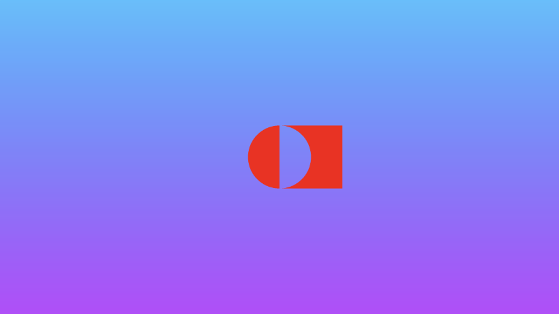
We can also create “smooth” 2D SDF operations that smoothly blend the edges around where the shapes meet. You’ll find these operations to be more applicable when I discuss 3D shapes, but they work in 2D too!
Add the following functions to the top of your code:
 1// smooth min
 2float smin(float a, float b, float k) {
 3  float h = clamp(0.5+0.5*(b-a)/k, 0.0, 1.0);
 4  return mix(b, a, h) - k*h*(1.0-h);
 5}
 6
 7// smooth max
 8float smax(float a, float b, float k) {
 9  return -smin(-a, -b, k);
10}
Smooth union: combine two shapes together, but smoothly blend the edges where they meet.
 1vec3 drawScene(vec2 uv) {
 2  vec3 col = getBackgroundColor(uv);
 3  float d1 = sdCircle(uv, 0.1, vec2(0., 0.));
 4  float d2 = sdSquare(uv, 0.1, vec2(0.1, 0));
 5
 6  float res; // result
 7  res = smin(d1, d2, 0.05); // smooth union
 8
 9  res = step(0., res); // Same as res > 0. ? 1. : 0.;
10
11  col = mix(vec3(1,0,0), col, res);
12  return col;
13}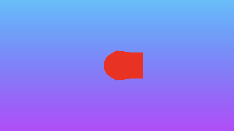
Smooth intersection: take only the two parts where the two shapes intersect, but smoothly blend the edges where they meet.
 1vec3 drawScene(vec2 uv) {
 2  vec3 col = getBackgroundColor(uv);
 3  float d1 = sdCircle(uv, 0.1, vec2(0., 0.));
 4  float d2 = sdSquare(uv, 0.1, vec2(0.1, 0));
 5
 6  float res; // result
 7  res = smax(d1, d2, 0.05); // smooth intersection
 8
 9  res = step(0., res); // Same as res > 0. ? 1. : 0.;
10
11  col = mix(vec3(1,0,0), col, res);
12  return col;
13}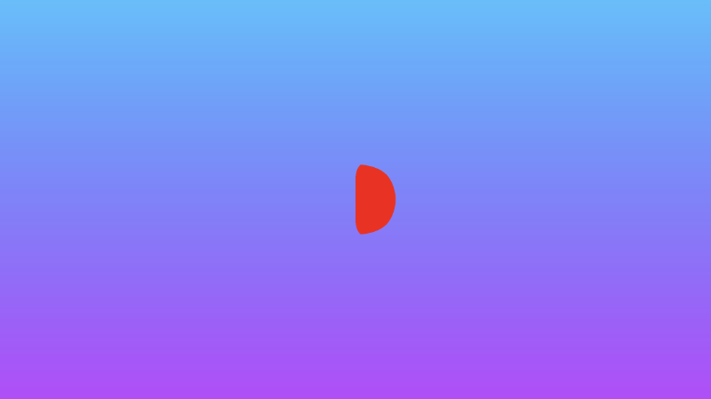
You can find the finished code below. Uncomment out the lines for any of the combination 2D SDF operations you want to see.
 1// smooth min
 2float smin(float a, float b, float k) {
 3  float h = clamp(0.5+0.5*(b-a)/k, 0.0, 1.0);
 4  return mix(b, a, h) - k*h*(1.0-h);
 5}
 6
 7// smooth max
 8float smax(float a, float b, float k) {
 9  return -smin(-a, -b, k);
10}
11
12vec3 getBackgroundColor(vec2 uv) {
13  uv = uv * 0.5 + 0.5; // remap uv from <-0.5,0.5> to <0.25,0.75>
14  vec3 gradientStartColor = vec3(1., 0., 1.);
15  vec3 gradientEndColor = vec3(0., 1., 1.);
16  return mix(gradientStartColor, gradientEndColor, uv.y); // gradient goes from bottom to top
17}
18
19float sdCircle(vec2 uv, float r, vec2 offset) {
20  float x = uv.x - offset.x;
21  float y = uv.y - offset.y;
22
23  return length(vec2(x, y)) - r;
24}
25
26float sdSquare(vec2 uv, float size, vec2 offset) {
27  float x = uv.x - offset.x;
28  float y = uv.y - offset.y;
29
30  return max(abs(x), abs(y)) - size;
31}
32
33vec3 drawScene(vec2 uv) {
34  vec3 col = getBackgroundColor(uv);
35  float d1 = sdCircle(uv, 0.1, vec2(0., 0.));
36  float d2 = sdSquare(uv, 0.1, vec2(0.1, 0));
37
38  float res; // result
39  res = d1;
40  //res = d2;
41  //res = min(d1, d2); // union
42  //res = max(d1, d2); // intersection
43  //res = max(-d1, d2); // subtraction - subtract d1 from d2
44  //res = max(d1, -d2); // subtraction - subtract d2 from d1
45  //res = max(min(d1, d2), -max(d1, d2)); // xor
46  //res = smin(d1, d2, 0.05); // smooth union
47  //res = smax(d1, d2, 0.05); // smooth intersection
48
49  res = step(0., res); // Same as res > 0. ? 1. : 0.;
50
51  col = mix(vec3(1,0,0), col, res);
52  return col;
53}
54
55void mainImage( out vec4 fragColor, in vec2 fragCoord )
56{
57  vec2 uv = fragCoord/iResolution.xy; // <0, 1>
58  uv -= 0.5; // <-0.5,0.5>
59  uv.x *= iResolution.x/iResolution.y; // fix aspect ratio
60
61  vec3 col = drawScene(uv);
62
63  fragColor = vec4(col,1.0); // Output to screen
64}
Positional 2D SDF Operations
Inigo Quilez’s 3D SDFs page describes a set of positional 3D SDF operations, but we can use these operations in 2D as well. I discuss 3D SDF operations later in Part 14. In this tutorial, I’ll go over positional 2D SDF operations that can help save us time and increase performance when drawing 2D shapes.
If you’re drawing a symmetrical scene, then it may be useful to use the opSymX operation. This operation will create a duplicate 2D shape along the x-axis using the SDF you provide. If we draw a circle at an offset of vec2(0.2, 0), then an equivalent circle will be drawn at vec2(-0.2, 0).
 1float opSymX(vec2 p, float r)
 2{
 3  p.x = abs(p.x);
 4  return sdCircle(p, r, vec2(0.2, 0));
 5}
 6
 7vec3 drawScene(vec2 uv) {
 8  vec3 col = getBackgroundColor(uv);
 9
10  float res; // result
11  res = opSymX(uv, 0.1);
12
13  res = step(0., res);
14  col = mix(vec3(1,0,0), col, res);
15  return col;
16}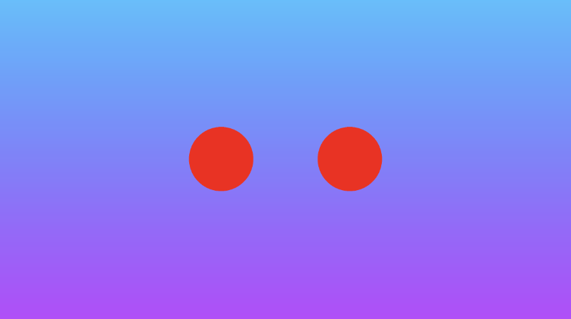
We can also perform a similar operation along the y-axis. Using the opSymY operation, if we draw a circle at an offset of vec2(0, 0.2), then an equivalent circle will be drawn at vec2(0, -0.2).
 1float opSymY(vec2 p, float r)
 2{
 3  p.y = abs(p.y);
 4  return sdCircle(p, r, vec2(0, 0.2));
 5}
 6
 7vec3 drawScene(vec2 uv) {
 8  vec3 col = getBackgroundColor(uv);
 9
10  float res; // result
11  res = opSymY(uv, 0.1);
12
13  res = step(0., res);
14  col = mix(vec3(1,0,0), col, res);
15  return col;
16}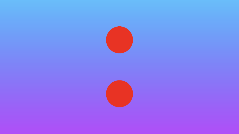
If you want to draw circles along two axes instead of just one, then you can use the opSymXY operation. This will create a duplicate along both the x-axis and y-axis, resulting in four circles. If we draw a circle with an offset of vec2(0.2, 0), then a circle will be drawn at vec2(0.2, 0.2), vec2(0.2, -0.2), vec2(-0.2, -0.2), and vec2(-0.2, 0.2).
 1float opSymXY(vec2 p, float r)
 2{
 3  p = abs(p);
 4  return sdCircle(p, r, vec2(0.2));
 5}
 6
 7vec3 drawScene(vec2 uv) {
 8  vec3 col = getBackgroundColor(uv);
 9
10  float res; // result
11  res = opSymXY(uv, 0.1);
12
13  res = step(0., res);
14  col = mix(vec3(1,0,0), col, res);
15  return col;
16}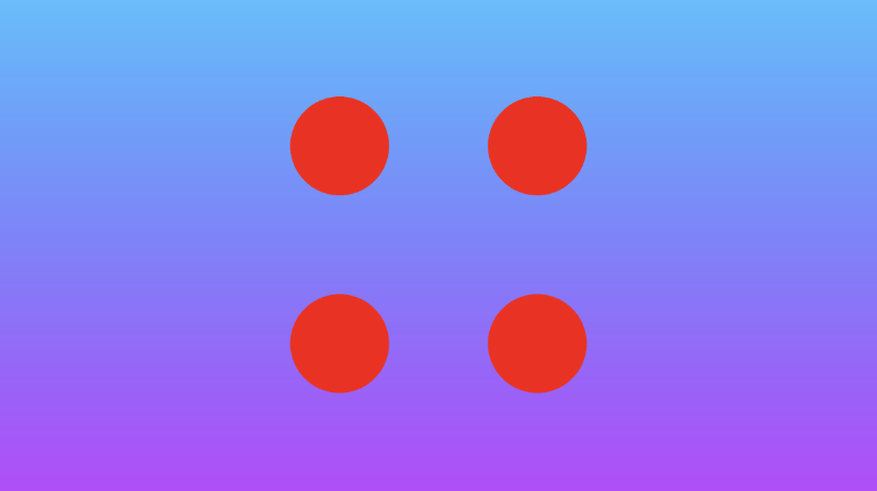
Sometimes, you may want to create an infinite number of 2D objects across one or more axes. You can use the opRep operation to repeat circles along the axes of your choice. The parameter, c, is a vector used to control the spacing between the 2D objects along each axis.
 1float opRep(vec2 p, float r, vec2 c)
 2{
 3  vec2 q = mod(p+0.5*c,c)-0.5*c;
 4  return sdCircle(q, r, vec2(0));
 5}
 6
 7vec3 drawScene(vec2 uv) {
 8  vec3 col = getBackgroundColor(uv);
 9
10  float res; // result
11  res = opRep(uv, 0.05, vec2(0.2, 0.2));
12
13  res = step(0., res);
14  col = mix(vec3(1,0,0), col, res);
15  return col;
16}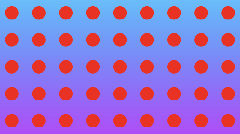
If you want to repeat the 2D objects only a certain number of times instead of an infinite amount, you can use the opRepLim operation. The parameter, c, is now a float value and still controls the spacing between each repeated 2D object. The parameter, l, is a vector that lets you control how many times the shape should be repeated along a given axis. For example, a value of vec2(2, 2) would draw an extra circle along the positive and negative x-axis and y-axis.
 1float opRepLim(vec2 p, float r, float c, vec2 l)
 2{
 3  vec2 q = p-c*clamp(round(p/c),-l,l);
 4  return sdCircle(q, r, vec2(0));
 5}
 6
 7vec3 drawScene(vec2 uv) {
 8  vec3 col = getBackgroundColor(uv);
 9
10  float res; // result
11  res = opRepLim(uv, 0.05, 0.15, vec2(2, 2));
12
13  res = step(0., res);
14  col = mix(vec3(1,0,0), col, res);
15  return col;
16}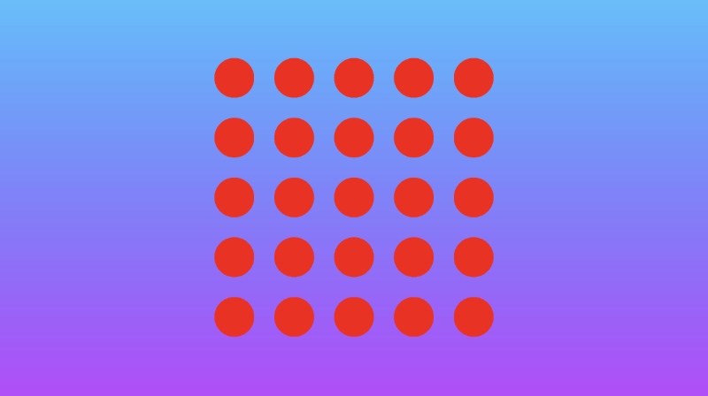
You can also perform deformations or distortions to an SDF by manipulating the value of p, the uv coordinate, and adding it to the value returned from an SDF. Inside the opDisplace operation, you can create any type of mathematical operation you want to displace the value of p and then add that result to the original value you get back from an SDF.
 1float opDisplace(vec2 p, float r)
 2{
 3  float d1 = sdCircle(p, r, vec2(0));
 4  float s = 0.5; // scaling factor
 5
 6  float d2 = sin(s * p.x * 1.8); // Some arbitrary values I played around with
 7
 8  return d1 + d2;
 9}
10
11vec3 drawScene(vec2 uv) {
12  vec3 col = getBackgroundColor(uv);
13
14  float res; // result
15  res = opDisplace(uv, 0.1); // Kinda looks like an egg
16
17  res = step(0., res);
18  col = mix(vec3(1,0,0), col, res);
19  return col;
20}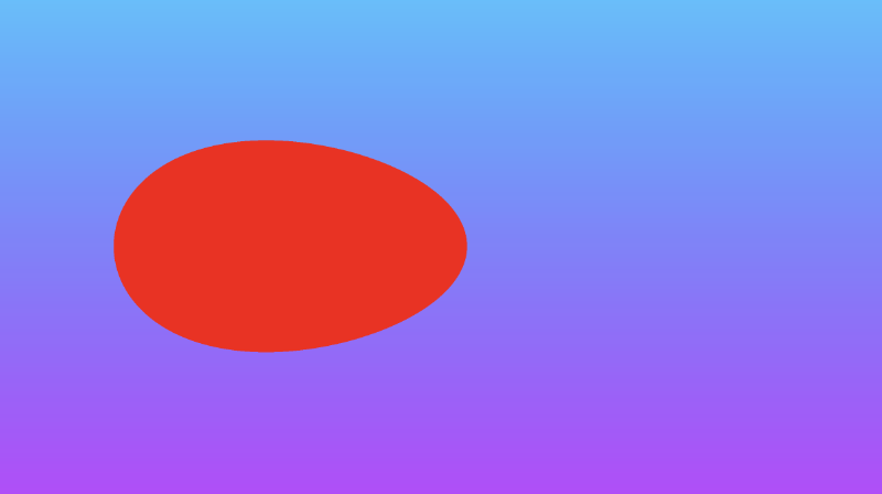
You can find the finished code below. Uncomment out the lines for any of the positional 2D SDF operations you want to see.
 1vec3 getBackgroundColor(vec2 uv) {
 2  uv = uv * 0.5 + 0.5; // remap uv from <-0.5,0.5> to <0.25,0.75>
 3  vec3 gradientStartColor = vec3(1., 0., 1.);
 4  vec3 gradientEndColor = vec3(0., 1., 1.);
 5  return mix(gradientStartColor, gradientEndColor, uv.y); // gradient goes from bottom to top
 6}
 7
 8float sdCircle(vec2 uv, float r, vec2 offset) {
 9  float x = uv.x - offset.x;
10  float y = uv.y - offset.y;
11
12  return length(vec2(x, y)) - r;
13}
14
15float opSymX(vec2 p, float r)
16{
17  p.x = abs(p.x);
18  return sdCircle(p, r, vec2(0.2, 0));
19}
20
21float opSymY(vec2 p, float r)
22{
23  p.y = abs(p.y);
24  return sdCircle(p, r, vec2(0, 0.2));
25}
26
27float opSymXY(vec2 p, float r)
28{
29  p = abs(p);
30  return sdCircle(p, r, vec2(0.2));
31}
32
33float opRep(vec2 p, float r, vec2 c)
34{
35  vec2 q = mod(p+0.5*c,c)-0.5*c;
36  return sdCircle(q, r, vec2(0));
37}
38
39float opRepLim(vec2 p, float r, float c, vec2 l)
40{
41  vec2 q = p-c*clamp(round(p/c),-l,l);
42  return sdCircle(q, r, vec2(0));
43}
44
45float opDisplace(vec2 p, float r)
46{
47  float d1 = sdCircle(p, r, vec2(0));
48  float s = 0.5; // scaling factor
49
50  float d2 = sin(s * p.x * 1.8); // Some arbitrary values I played around with
51
52  return d1 + d2;
53}
54
55vec3 drawScene(vec2 uv) {
56  vec3 col = getBackgroundColor(uv);
57
58  float res; // result
59  res = opSymX(uv, 0.1);
60  //res = opSymY(uv, 0.1);
61  //res = opSymXY(uv, 0.1);
62  //res = opRep(uv, 0.05, vec2(0.2, 0.2));
63  //res = opRepLim(uv, 0.05, 0.15, vec2(2, 2));
64  //res = opDisplace(uv, 0.1);
65
66  res = step(0., res);
67  col = mix(vec3(1,0,0), col, res);
68  return col;
69}
70
71void mainImage( out vec4 fragColor, in vec2 fragCoord )
72{
73  vec2 uv = fragCoord/iResolution.xy; // <0, 1>
74  uv -= 0.5; // <-0.5,0.5>
75  uv.x *= iResolution.x/iResolution.y; // fix aspect ratio
76
77  vec3 col = drawScene(uv);
78
79  fragColor = vec4(col,1.0); // Output to screen
80}
Anti-aliasing
If you want to add any anti-aliasing, then you can use the smoothstep function to smooth out the edges of your shapes. The smoothstep(edge0, edge1, x) function accepts three parameters and performs a Hermite interpolation between zero and one when edge0 < x < edge1 .
1edge0: Specifies the value of the lower edge of the Hermite function.
2
3edge1: Specifies the value of the upper edge of the Hermite function.
4
5x: Specifies the source value for interpolation.
6
7t = clamp((x - edge0) / (edge1 - edge0), 0.0, 1.0);
8return t * t * (3.0 - 2.0 * t);
TIP
The docs will say if
edge0is greater than or equal toedge1, then thesmoothstepfunction will return a value ofundefined. However, this is incorrect. The result of thesmoothstepfunction is still determined by the Hermite interpolation function even ifedge0is greater thanedge1.
If you’re still confused, this page from The Book of Shaders may help you visualize the smoothstep function. Essentially, it behaves like the step function with a few extra steps (no pun intended) 😂.
Let’s replace the step function with the smoothstep function to see how the result between a union of a circle and square behaves.
 1vec3 getBackgroundColor(vec2 uv) {
 2  uv = uv * 0.5 + 0.5; // remap uv from <-0.5,0.5> to <0.25,0.75>
 3  vec3 gradientStartColor = vec3(1., 0., 1.);
 4  vec3 gradientEndColor = vec3(0., 1., 1.);
 5  return mix(gradientStartColor, gradientEndColor, uv.y); // gradient goes from bottom to top
 6}
 7
 8float sdCircle(vec2 uv, float r, vec2 offset) {
 9  float x = uv.x - offset.x;
10  float y = uv.y - offset.y;
11
12  return length(vec2(x, y)) - r;
13}
14
15float sdSquare(vec2 uv, float size, vec2 offset) {
16  float x = uv.x - offset.x;
17  float y = uv.y - offset.y;
18
19  return max(abs(x), abs(y)) - size;
20}
21
22vec3 drawScene(vec2 uv) {
23  vec3 col = getBackgroundColor(uv);
24  float d1 = sdCircle(uv, 0.1, vec2(0., 0.));
25  float d2 = sdSquare(uv, 0.1, vec2(0.1, 0));
26
27  float res; // result
28  res = min(d1, d2); // union
29
30  res = smoothstep(0., 0.02, res); // antialias entire result
31
32  col = mix(vec3(1,0,0), col, res);
33  return col;
34}
35
36void mainImage( out vec4 fragColor, in vec2 fragCoord )
37{
38  vec2 uv = fragCoord/iResolution.xy; // <0, 1>
39  uv -= 0.5; // <-0.5,0.5>
40  uv.x *= iResolution.x/iResolution.y; // fix aspect ratio
41
42  vec3 col = drawScene(uv);
43
44  fragColor = vec4(col,1.0); // Output to screen
45}
We end up with a shape that is slightly blurred around the edges.

The smoothstep function helps us create smooth transitions between colors, useful for implementing anti-aliasing. You may also see people use smoothstep to create emissive objects or neon glow effects. It is used very often in shaders.
Drawing a Heart ❤️
In this section, I’ll teach you how to draw a heart using Shadertoy. Keep in mind that there are multiple styles of hearts. I’ll show you how to create just one particular style of heart using an equation from Wolfram MathWorld.
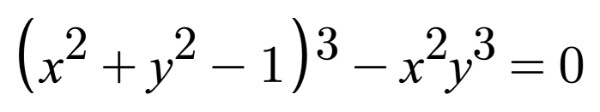
If we want to apply an offset to this heart curve, then we need to subtract it from the x-component and y-component before applying any sort of operation (such as exponentiation) on them.
s = x - offsetX
t = y - offsetY

(s^2 + t^2 - 1)^3 - s^2 * t^3 = 0

x = x-coordinate on graph
y = y-coordinate on graph
You can play around with offsets on a heart curve using the graph I created on Desmos.
Now, how do we create an SDF for a heart in Shadertoy? We simply set the left-hand side (LHS) of the equation equal to the distance, d. Then, it’s the same process as we learned in Part 4.
 1float sdHeart(vec2 uv, float size, vec2 offset) {
 2  float x = uv.x - offset.x;
 3  float y = uv.y - offset.y;
 4  float xx = x * x;
 5  float yy = y * y;
 6  float yyy = yy * y;
 7  float group = xx + yy - size;
 8  float d = group * group * group - xx * yyy;
 9
10  return d;
11}
12
13vec3 drawScene(vec2 uv) {
14  vec3 col = vec3(1);
15  float heart = sdHeart(uv, 0.04, vec2(0));
16
17  col = mix(vec3(1, 0, 0), col, step(0., heart));
18
19  return col;
20}
21
22void mainImage( out vec4 fragColor, in vec2 fragCoord )
23{
24  vec2 uv = fragCoord/iResolution.xy; // <0, 1>
25  uv -= 0.5; // <-0.5,0.5>
26  uv.x *= iResolution.x/iResolution.y; // fix aspect ratio
27
28  vec3 col = drawScene(uv);
29
30  // Output to screen
31  fragColor = vec4(col,1.0);
32}
Understanding the pow Function
You may be wondering why I created the sdHeart function in such a weird manner. Why not use the pow function that is available to us? The pow(x,y) function takes in a value, x, and raises it to the power of y.
If you tried using the pow function, you’ll see right away how odd the heart behaves.
1float sdHeart(vec2 uv, float size, vec2 offset) {
2  float x = uv.x - offset.x;
3  float y = uv.y - offset.y;
4  float group = pow(x,2.) + pow(y,2.) - size;
5  float d = pow(group,3.) - pow(x,2.) * pow(y,3.);
6
7  return d;
8}
Well, that doesn’t look right 🤔. If you sent that to someone on Valentine’s Day, they might think it’s an inkblot test.
So why does the pow(x,y) function behave so strangely? If you look closer at the documentation for this function, then you’ll see that this function returns undefined if x is less than zero or if both x equals zero and y is less than or equal to zero.
Keep in mind that the implementation of the pow function varies by compiler and hardware, so you may not encounter this issue when developing shaders for other platforms outside Shadertoy, or you may experience different issues.
Because our coordinate system is set up to have negative values for x and y, we sometimes get undefined as a result of the pow function. In Shadertoy, the compiler will use undefined in mathematical operations which will then lead to confusing results.
We can experiment with how undefined behaves with different arithmetic operations by debugging the canvas using color. Let’s try adding a number to undefined:
 1void mainImage( out vec4 fragColor, in vec2 fragCoord )
 2{
 3  vec2 uv = fragCoord/iResolution.xy; // <0, 1>
 4  uv -= 0.5; // <-0.5,0.5>
 5
 6  vec3 col = vec3(pow(-0.5, 1.));
 7  col += 0.5;
 8
 9  fragColor = vec4(col,1.0);
10  // Screen is gray which means undefined is treated as zero
11}
Let’s try subtracting a number from undefined:
 1void mainImage( out vec4 fragColor, in vec2 fragCoord )
 2{
 3  vec2 uv = fragCoord/iResolution.xy; // <0, 1>
 4  uv -= 0.5; // <-0.5,0.5>
 5
 6  vec3 col = vec3(pow(-0.5, 1.));
 7  col -= -0.5;
 8
 9  fragColor = vec4(col,1.0);
10  // Screen is gray which means undefined is treated as zero
11}
Let’s try multiplying a number by undefined:
 1void mainImage( out vec4 fragColor, in vec2 fragCoord )
 2{
 3  vec2 uv = fragCoord/iResolution.xy; // <0, 1>
 4  uv -= 0.5; // <-0.5,0.5>
 5
 6  vec3 col = vec3(pow(-0.5, 1.));
 7  col *= 1.;
 8
 9  fragColor = vec4(col,1.0);
10  // Screen is black which means undefined is treated as zero
11}
Let’s try dividing undefined by a number:
 1void mainImage( out vec4 fragColor, in vec2 fragCoord )
 2{
 3  vec2 uv = fragCoord/iResolution.xy; // <0, 1>
 4  uv -= 0.5; // <-0.5,0.5>
 5
 6  vec3 col = vec3(pow(-0.5, 1.));
 7  col /= 1.;
 8
 9  fragColor = vec4(col,1.0);
10  // Screen is black which means undefined is treated as zero
11}
From the observations we’ve gathered, we can conclude that undefined is treated as a value of zero when used in arithmetic operations. However, this could still vary by compiler and graphics hardware. Therefore, you need to be careful how you use the pow function in your shader code.
If you want to square a value, a common trick is to use the dot function to compute the dot product between a vector and itself. This lets us rewrite the sdHeart function to be a bit cleaner:
1float sdHeart(vec2 uv, float size, vec2 offset) {
2  float x = uv.x - offset.x;
3  float y = uv.y - offset.y;
4  float group = dot(x,x) + dot(y,y) - size;
5  float d = group * dot(group, group) - dot(x,x) * dot(y,y) * y;
6
7  return d;
8}
Calling dot(x,x) is the same as squaring the value of x, but you don’t have to deal with the hassles of the pow function.
Using the sdStar5 SDF
Inigo Quilez has created many 2D SDFs and 3D SDFs that developers across Shadertoy utilize. In this section, I’ll discuss how we can use his 2D SDF list together with techniques we learned in Part 4 of my Shadertoy series to draw 2D shapes.
When creating shapes using SDFs, they are commonly referred to as “primitives” because they form the building blocks for creating more abstract shapes. For 2D, it’s pretty simple to draw shapes on the canvas, but it’ll become more complex when we discuss 3D shapes.
Let’s practice with a star SDF because drawing stars is always fun. Navigate to Inigo Quilez’s website and scroll down to the SDF called “Star 5 - exact”. It should have the following definition:
 1float sdStar5(in vec2 p, in float r, in float rf)
 2{
 3  const vec2 k1 = vec2(0.809016994375, -0.587785252292);
 4  const vec2 k2 = vec2(-k1.x,k1.y);
 5  p.x = abs(p.x);
 6  p -= 2.0*max(dot(k1,p),0.0)*k1;
 7  p -= 2.0*max(dot(k2,p),0.0)*k2;
 8  p.x = abs(p.x);
 9  p.y -= r;
10  vec2 ba = rf*vec2(-k1.y,k1.x) - vec2(0,1);
11  float h = clamp( dot(p,ba)/dot(ba,ba), 0.0, r );
12  return length(p-ba*h) * sign(p.y*ba.x-p.x*ba.y);
13}
Don’t worry about the in qualifiers in the function. You can remove them if you want, since in is the default qualifier if none is specified.
Let’s create a new Shadertoy shader with the following code:
1float sdStar5(in vec2 p, in float r, in float rf)
2{
3 const vec2 k1 = vec2(0.809016994375, -0.587785252292);
4 const vec2 k2 = vec2(-k1.x,k1.y);
5 p.x = abs(p.x);
6 p -= 2.0*max(dot(k1,p),0.0)*k1;
7 p -= 2.0*max(dot(k2,p),0.0)*k2;
8 p.x = abs(p.x);
9 p.y -= r;
10 vec2 ba = rf*vec2(-k1.y,k1.x) - vec2(0,1);
11 float h = clamp( dot(p,ba)/dot(ba,ba), 0.0, r );
12 return length(p-ba*h) * sign(p.y*ba.x-p.x*ba.y);
13}
14
15vec3 drawScene(vec2 uv) {
16 vec3 col = vec3(0);
17 float star = sdStar5(uv, 0.12, 0.45);
18
19 col = mix(vec3(1, 1, 0), col, step(0., star));
20
21 return col;
22}
23
24void mainImage( out vec4 fragColor, in vec2 fragCoord )
25{
26 vec2 uv = fragCoord/iResolution.xy; // <0, 1>
27 uv -= 0.5; // <-0.5,0.5>
28 uv.x *= iResolution.x/iResolution.y; // fix aspect ratio
29
30 vec3 col = drawScene(uv);
31
32 // Output to screen
33 fragColor = vec4(col,1.0);
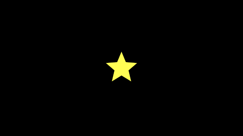
34}When we run this code, you should be able to see a bright yellow star! ⭐
One thing is missing though. We need to add an offset at the beginning of the sdStar5 function by shifting the UV coordinates a bit. We can add a new parameter called offset, and we can subtract this offset from the vector, p, which represents the UV coordinates we passed into this function.
Our finished code should like this this:
 1float sdStar5(in vec2 p, in float r, in float rf, vec2 offset)
 2{
 3  p -= offset; // This will subtract offset.x from p.x and subtract offset.y from p.y
 4  const vec2 k1 = vec2(0.809016994375, -0.587785252292);
 5  const vec2 k2 = vec2(-k1.x,k1.y);
 6  p.x = abs(p.x);
 7  p -= 2.0*max(dot(k1,p),0.0)*k1;
 8  p -= 2.0*max(dot(k2,p),0.0)*k2;
 9  p.x = abs(p.x);
10  p.y -= r;
11  vec2 ba = rf*vec2(-k1.y,k1.x) - vec2(0,1);
12  float h = clamp( dot(p,ba)/dot(ba,ba), 0.0, r );
13  return length(p-ba*h) * sign(p.y*ba.x-p.x*ba.y);
14}
15
16vec3 drawScene(vec2 uv) {
17  vec3 col = vec3(0);
18  float star = sdStar5(uv, 0.12, 0.45, vec2(0.2, 0)); // Add an offset to shift the star's position
19
20  col = mix(vec3(1, 1, 0), col, step(0., star));
21
22  return col;
23}
24
25void mainImage( out vec4 fragColor, in vec2 fragCoord )
26{
27  vec2 uv = fragCoord/iResolution.xy; // <0, 1>
28  uv -= 0.5; // <-0.5,0.5>
29  uv.x *= iResolution.x/iResolution.y; // fix aspect ratio
30
31  vec3 col = drawScene(uv);
32
33  // Output to screen
34  fragColor = vec4(col,1.0);
35}
Using the sdBox SDF
It’s quite common to draw boxes/rectangles, so we’ll select the SDF titled “Box - exact.” It has the following definition:
1float sdBox( in vec2 p, in vec2 b )
2{
3  vec2 d = abs(p)-b;
4  return length(max(d,0.0)) + min(max(d.x,d.y),0.0);
5}
We’ll add an offset parameter to the function declaration.
1float sdBox( in vec2 p, in vec2 b, vec2 offset )
2{
3  p -= offset;
4  vec2 d = abs(p)-b;
5  return length(max(d,0.0)) + min(max(d.x,d.y),0.0);
6}
Now, we should be able to render both the box and star without any issues:
 1float sdBox( in vec2 p, in vec2 b, vec2 offset )
 2{
 3  p -= offset;
 4  vec2 d = abs(p)-b;
 5  return length(max(d,0.0)) + min(max(d.x,d.y),0.0);
 6}
 7
 8float sdStar5(in vec2 p, in float r, in float rf, vec2 offset)
 9{
10  p -= offset; // This will subtract offset.x from p.x and subtract offset.y from p.y
11  const vec2 k1 = vec2(0.809016994375, -0.587785252292);
12  const vec2 k2 = vec2(-k1.x,k1.y);
13  p.x = abs(p.x);
14  p -= 2.0*max(dot(k1,p),0.0)*k1;
15  p -= 2.0*max(dot(k2,p),0.0)*k2;
16  p.x = abs(p.x);
17  p.y -= r;
18  vec2 ba = rf*vec2(-k1.y,k1.x) - vec2(0,1);
19  float h = clamp( dot(p,ba)/dot(ba,ba), 0.0, r );
20  return length(p-ba*h) * sign(p.y*ba.x-p.x*ba.y);
21}
22
23vec3 drawScene(vec2 uv) {
24  vec3 col = vec3(0);
25  float box = sdBox(uv, vec2(0.2, 0.1), vec2(-0.2, 0));
26  float star = sdStar5(uv, 0.12, 0.45, vec2(0.2, 0));
27
28  col = mix(vec3(1, 1, 0), col, step(0., star));
29  col = mix(vec3(0, 0, 1), col, step(0., box));
30
31  return col;
32}
33
34void mainImage( out vec4 fragColor, in vec2 fragCoord )
35{
36  vec2 uv = fragCoord/iResolution.xy; // <0, 1>
37  uv -= 0.5; // <-0.5,0.5>
38  uv.x *= iResolution.x/iResolution.y; // fix aspect ratio
39
40  vec3 col = drawScene(uv);
41
42  // Output to screen
43  fragColor = vec4(col,1.0);
44}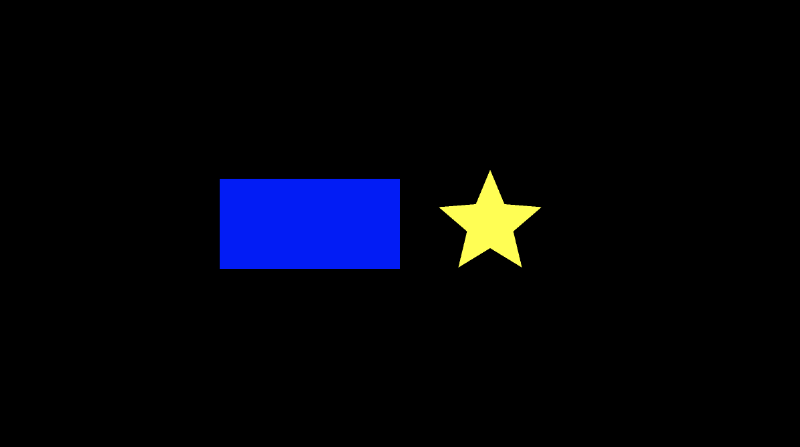
With only a few small tweaks, we can pick many 2D SDFs from Inigo Quilez’s website and draw them to the canvas with an offset.
Note, however, that some of the SDFs require functions defined on his 3D SDF page:
1float dot2( in vec2 v ) { return dot(v,v); }
2float dot2( in vec3 v ) { return dot(v,v); }
3float ndot( in vec2 a, in vec2 b ) { return a.x*b.x - a.y*b.y; }
Using the sdSegment SDF
Some of the 2D SDFs on Inigo Quilez’s website are for segments or curves, so we may need to alter our approach slightly. Let’s look at the SDF titled “Segment - exact”. It has the following definition:
1float sdSegment( in vec2 p, in vec2 a, in vec2 b )
2{
3  vec2 pa = p-a, ba = b-a;
4  float h = clamp( dot(pa,ba)/dot(ba,ba), 0.0, 1.0 );
5  return length( pa - ba*h );
6}
Let’s try using this SDF and see what happens.
 1float sdSegment( in vec2 p, in vec2 a, in vec2 b )
 2{
 3  vec2 pa = p-a, ba = b-a;
 4  float h = clamp( dot(pa,ba)/dot(ba,ba), 0.0, 1.0 );
 5  return length( pa - ba*h );
 6}
 7
 8vec3 drawScene(vec2 uv) {
 9  vec3 col = vec3(0);
10  float segment = sdSegment(uv, vec2(0, 0), vec2(0, .2));
11
12  col = mix(vec3(1, 1, 1), col, step(0., segment));
13
14  return col;
15}
16
17void mainImage( out vec4 fragColor, in vec2 fragCoord )
18{
19  vec2 uv = fragCoord/iResolution.xy; // <0, 1>
20  uv -= 0.5; // <-0.5,0.5>
21  uv.x *= iResolution.x/iResolution.y; // fix aspect ratio
22
23  vec3 col = drawScene(uv);
24
25  // Output to screen
26  fragColor = vec4(col,1.0);
27}
When we run this code, we’ll see a completely black canvas. Some SDFs require us to look at the code a bit more closely. Currently, the segment is too thin to see in our canvas. To give the segment some thickness, we can subtract a value from the returned distance.
 1float sdSegment( in vec2 p, in vec2 a, in vec2 b )
 2{
 3  vec2 pa = p-a, ba = b-a;
 4  float h = clamp( dot(pa,ba)/dot(ba,ba), 0.0, 1.0 );
 5  return length( pa - ba*h );
 6}
 7
 8vec3 drawScene(vec2 uv) {
 9  vec3 col = vec3(0);
10  float segment = sdSegment(uv, vec2(0, 0), vec2(0, 0.2));
11
12  col = mix(vec3(1, 1, 1), col, step(0., segment - 0.02)); // Subtract 0.02 from the returned "signed distance" value of the segment
13
14  return col;
15}
16
17void mainImage( out vec4 fragColor, in vec2 fragCoord )
18{
19  vec2 uv = fragCoord/iResolution.xy; // <0, 1>
20  uv -= 0.5; // <-0.5,0.5>
21  uv.x *= iResolution.x/iResolution.y; // fix aspect ratio
22
23  vec3 col = drawScene(uv);
24
25  // Output to screen
26  fragColor = vec4(col,1.0);
27}
Now, we can see our segment appear! It starts at the coordinate, (0, 0), and ends at (0, 0.2). Play around with the input vectors, a and b, inside the call to the sdSegment function to move the segment around and stretch it different ways. You can replace 0.02 with another number if you want to make the segment thinner or wider.

You can also use the smoothstep function to make the segment look blurry around the edges.
 1float sdSegment( in vec2 p, in vec2 a, in vec2 b )
 2{
 3  vec2 pa = p-a, ba = b-a;
 4  float h = clamp( dot(pa,ba)/dot(ba,ba), 0.0, 1.0 );
 5  return length( pa - ba*h );
 6}
 7
 8vec3 drawScene(vec2 uv) {
 9  vec3 col = vec3(0);
10  float segment = sdSegment(uv, vec2(0, 0), vec2(0, .2));
11
12  col = mix(vec3(1, 1, 1), col, smoothstep(0., 0.02, segment));
13
14  return col;
15}
16
17void mainImage( out vec4 fragColor, in vec2 fragCoord )
18{
19  vec2 uv = fragCoord/iResolution.xy; // <0, 1>
20  uv -= 0.5; // <-0.5,0.5>
21  uv.x *= iResolution.x/iResolution.y; // fix aspect ratio
22
23  vec3 col = drawScene(uv);
24
25  // Output to screen
26  fragColor = vec4(col,1.0);
27}
The segment now looks like it’s glowing!
Using the sdBezier SDF
Inigo Quilez’s website also has an SDF for Bézier curves. More specifically, he has an SDF for a Quadratic Bézier curve. Look for the SDF titled “Quadratic Bezier - exact”. It has the following definition:
 1float sdBezier( in vec2 pos, in vec2 A, in vec2 B, in vec2 C )
 2{
 3    vec2 a = B - A;
 4    vec2 b = A - 2.0*B + C;
 5    vec2 c = a * 2.0;
 6    vec2 d = A - pos;
 7    float kk = 1.0/dot(b,b);
 8    float kx = kk * dot(a,b);
 9    float ky = kk * (2.0*dot(a,a)+dot(d,b)) / 3.0;
10    float kz = kk * dot(d,a);
11    float res = 0.0;
12    float p = ky - kx*kx;
13    float p3 = p*p*p;
14    float q = kx*(2.0*kx*kx-3.0*ky) + kz;
15    float h = q*q + 4.0*p3;
16    if( h >= 0.0)
17    {
18        h = sqrt(h);
19        vec2 x = (vec2(h,-h)-q)/2.0;
20        vec2 uv = sign(x)*pow(abs(x), vec2(1.0/3.0));
21        float t = clamp( uv.x+uv.y-kx, 0.0, 1.0 );
22        res = dot2(d + (c + b*t)*t);
23    }
24    else
25    {
26        float z = sqrt(-p);
27        float v = acos( q/(p*z*2.0) ) / 3.0;
28        float m = cos(v);
29        float n = sin(v)*1.732050808;
30        vec3  t = clamp(vec3(m+m,-n-m,n-m)*z-kx,0.0,1.0);
31        res = min( dot2(d+(c+b*t.x)*t.x),
32                   dot2(d+(c+b*t.y)*t.y) );
33        // the third root cannot be the closest
34        // res = min(res,dot2(d+(c+b*t.z)*t.z));
35    }
36    return sqrt( res );
37}
That’s quite a large function! Notice that this function uses a utility function, dot2. This is defined on his 3D SDF page.
1float dot2( in vec2 v ) { return dot(v,v); }Quadratic Bézier curves accept three control points. In 2D, each control point will be a vec2 value with an x-component and y-component. You can play around with the control points using a graph I created on Desmos.
Like the sdSegment, we will have to subtract a small value from the returned “signed distance” to see the curve properly. Let’s see how to draw a Quadratic Bézier curve using GLSL code:
 1float dot2( in vec2 v ) { return dot(v,v); }
 2
 3float sdBezier( in vec2 pos, in vec2 A, in vec2 B, in vec2 C )
 4{
 5    vec2 a = B - A;
 6    vec2 b = A - 2.0*B + C;
 7    vec2 c = a * 2.0;
 8    vec2 d = A - pos;
 9    float kk = 1.0/dot(b,b);
10    float kx = kk * dot(a,b);
11    float ky = kk * (2.0*dot(a,a)+dot(d,b)) / 3.0;
12    float kz = kk * dot(d,a);
13    float res = 0.0;
14    float p = ky - kx*kx;
15    float p3 = p*p*p;
16    float q = kx*(2.0*kx*kx-3.0*ky) + kz;
17    float h = q*q + 4.0*p3;
18    if( h >= 0.0)
19    {
20        h = sqrt(h);
21        vec2 x = (vec2(h,-h)-q)/2.0;
22        vec2 uv = sign(x)*pow(abs(x), vec2(1.0/3.0));
23        float t = clamp( uv.x+uv.y-kx, 0.0, 1.0 );
24        res = dot2(d + (c + b*t)*t);
25    }
26    else
27    {
28        float z = sqrt(-p);
29        float v = acos( q/(p*z*2.0) ) / 3.0;
30        float m = cos(v);
31        float n = sin(v)*1.732050808;
32        vec3  t = clamp(vec3(m+m,-n-m,n-m)*z-kx,0.0,1.0);
33        res = min( dot2(d+(c+b*t.x)*t.x),
34                   dot2(d+(c+b*t.y)*t.y) );
35        // the third root cannot be the closest
36        // res = min(res,dot2(d+(c+b*t.z)*t.z));
37    }
38    return sqrt( res );
39}
40
41vec3 drawScene(vec2 uv) {
42    vec3 col = vec3(0);
43    vec2 A = vec2(0, 0);
44    vec2 B = vec2(0.2, 0);
45    vec2 C = vec2(0.2, 0.2);
46    float curve = sdBezier(uv, A, B, C);
47
48    col = mix(vec3(1, 1, 1), col, step(0., curve - 0.01));
49
50    return col;
51}
52
53void mainImage( out vec4 fragColor, in vec2 fragCoord )
54{
55    vec2 uv = fragCoord/iResolution.xy; // <0, 1>
56    uv -= 0.5; // <-0.5,0.5>
57    uv.x *= iResolution.x/iResolution.y; // fix aspect ratio
58
59
60    vec3 col = drawScene(uv);
61
62    // Output to screen
63    fragColor = vec4(col,1.0);
64}
When you run the code, you should see the Quadratic Bézier curve appear.
Try playing around with the control points! Remember! You can use my Desmos graph to help!
You can use 2D operations together with Bézier curves to create interesting effects. We can subtract two Bézier curves from a circle to get some kind of tennis ball 🎾. It’s up to you to explore what all you can create with the tools presented to you!

Below you can find the finished code used to make the tennis ball:
 1vec3 getBackgroundColor(vec2 uv) {
 2  uv = uv * 0.5 + 0.5; // remap uv from <-0.5,0.5> to <0.25,0.75>
 3  vec3 gradientStartColor = vec3(1., 0., 1.);
 4  vec3 gradientEndColor = vec3(0., 1., 1.);
 5  return mix(gradientStartColor, gradientEndColor, uv.y); // gradient goes from bottom to top
 6}
 7
 8float sdCircle(vec2 uv, float r, vec2 offset) {
 9  float x = uv.x - offset.x;
10  float y = uv.y - offset.y;
11
12  return length(vec2(x, y)) - r;
13}
14
15float dot2( in vec2 v ) { return dot(v,v); }
16
17float sdBezier( in vec2 pos, in vec2 A, in vec2 B, in vec2 C )
18{
19    vec2 a = B - A;
20    vec2 b = A - 2.0*B + C;
21    vec2 c = a * 2.0;
22    vec2 d = A - pos;
23    float kk = 1.0/dot(b,b);
24    float kx = kk * dot(a,b);
25    float ky = kk * (2.0*dot(a,a)+dot(d,b)) / 3.0;
26    float kz = kk * dot(d,a);
27    float res = 0.0;
28    float p = ky - kx*kx;
29    float p3 = p*p*p;
30    float q = kx*(2.0*kx*kx-3.0*ky) + kz;
31    float h = q*q + 4.0*p3;
32    if( h >= 0.0)
33    {
34        h = sqrt(h);
35        vec2 x = (vec2(h,-h)-q)/2.0;
36        vec2 uv = sign(x)*pow(abs(x), vec2(1.0/3.0));
37        float t = clamp( uv.x+uv.y-kx, 0.0, 1.0 );
38        res = dot2(d + (c + b*t)*t);
39    }
40    else
41    {
42        float z = sqrt(-p);
43        float v = acos( q/(p*z*2.0) ) / 3.0;
44        float m = cos(v);
45        float n = sin(v)*1.732050808;
46        vec3  t = clamp(vec3(m+m,-n-m,n-m)*z-kx,0.0,1.0);
47        res = min( dot2(d+(c+b*t.x)*t.x),
48                   dot2(d+(c+b*t.y)*t.y) );
49        // the third root cannot be the closest
50        // res = min(res,dot2(d+(c+b*t.z)*t.z));
51    }
52    return sqrt( res );
53}
54
55vec3 drawScene(vec2 uv) {
56  vec3 col = getBackgroundColor(uv);
57  float d1 = sdCircle(uv, 0.2, vec2(0., 0.));
58  vec2 A = vec2(-0.2, 0.2);
59  vec2 B = vec2(0, 0);
60  vec2 C = vec2(0.2, 0.2);
61  float d2 = sdBezier(uv, A, B, C) - 0.03;
62  float d3 = sdBezier(uv*vec2(1,-1), A, B, C) - 0.03;
63
64  float res; // result
65  res = max(d1, -d2); // subtraction - subtract d2 from d1
66  res = max(res, -d3); // subtraction - subtract d3 from the result
67
68  res = smoothstep(0., 0.01, res); // antialias entire result
69
70  col = mix(vec3(.8,.9,.2), col, res);
71  return col;
72}
73
74void mainImage( out vec4 fragColor, in vec2 fragCoord )
75{
76  vec2 uv = fragCoord/iResolution.xy; // <0, 1>
77  uv -= 0.5; // <-0.5,0.5>
78  uv.x *= iResolution.x/iResolution.y; // fix aspect ratio
79
80  vec3 col = drawScene(uv);
81
82  fragColor = vec4(col,1.0); // Output to screen
83}
Conclusion
In this tutorial, we learned how to show more love to our shaders by drawing a heart ❤️ and other shapes. We learned how to draw stars, segments, and Quadratic Bézier curves. Of course, my technique for drawing shapes with 2D SDFs is just a personal preference. There are multiple ways we can draw 2D shapes to the canvas. We also learned how to combine primitive shapes together to create more complex shapes. In the next article, we’ll begin learning how to draw 3D shapes and scenes using raymarching! 🎉
Resources
- List of 2D SDFs
- Khronos: pow
- Khronos: smoothstep
- Why does the pow function behave strangely?
- Book of Shaders: Smoothstep
- What happens when edge0 is greater than edge1?
- Shadertoy: Multiple 2D Shapes Example
Tutorial Part 6 - 3D Scenes with Ray Marching
转自:https://inspirnathan.com/posts/52-shadertoy-tutorial-part-6
Greetings, friends! It’s the moment you’ve all been waiting for! In this tutorial, you’ll take the first steps toward learning how to draw 3D scenes in Shadertoy using ray marching!
Introduction to Rays
Have you ever browsed across Shadertoy, only to see amazing creations that leave you in awe? How do people create such amazing scenes with only a pixel shader and no 3D models? Is it magic? Do they have a PhD in mathematics or graphics design? Some of them might, but most of them don’t!
Most of the 3D scenes you see on Shadertoy use some form of a ray tracing or ray marching algorithm. These algorithms are commonly used in the realm of computer graphics. The first step toward creating a 3D scene in Shadertoy is understanding rays.
Behold! The ray! 🙌
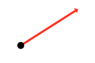
That’s it? It looks like a dot with an arrow pointing out it. Yep, indeed it is! The black dot represents the ray origin, and the red arrow represents that it’s pointing in a direction. You’ll be using rays a lot when creating 3D scenes, so it’s best to understand how they work.
A ray consists of an origin and direction, but what do I mean by that?
A ray origin is simply the starting point of the ray. In 2D, we can create a variable in GLSL to represent an origin:
1vec2 rayOrigin = vec2(0, 0);You may be confused if you’ve taken some linear algebra or calculus courses. Why are we assigning a point as a vector? Don’t all vectors have directions? Mathematically speaking, vectors have both a length and direction, but we’re talking about a vector data type in this context.
In shader languages such as GLSL, we can use a vec2 to store any two values we want in it as if it were an array (not to be confused with actual arrays in the GLSL language specification). In variables of type vec3, we can store three values. These values can represent a variety of things: color, coordinates, a circle radius, or whatever else you want. For a ray origin, we have chosen our values to represent an XY coordinate such as (0, 0).
A ray direction is a vector that is normalized such that it has a magnitude of one. In 2D, we can create a variable in GLSL to represent a direction:
1vec2 rayDirection = vec2(1, 0);By setting the ray direction equal to vec2(1, 0), we are saying that the ray is pointing one unit to the right.
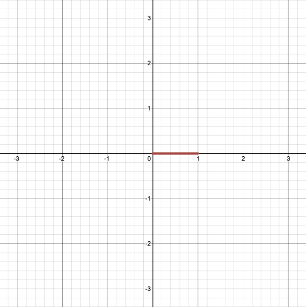
2D vectors can have an x-component and y-component. Here’s an example of a ray with a direction of vec2(2, 2) where the black line represents the ray. It’s pointing diagonally up and to the right at a 45 degree angle from the origin. The red horizontal line represents the x-component of the ray, and the green vertical line represents the y-component. You can play around with vectors using a graph I created in Desmos.
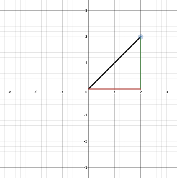
This ray is not normalized though. If we find the magnitude of the ray direction, we’ll discover that it’s not equal to one. The magnitude can be calculated using the following equation for 2D vectors:
Let’s calculate the magnitude (length) of the ray, vec2(2,2).
length(vec2(2,2)) = sqrt(x^2 + y^2) = sqrt(2^2 + 2^2) = sqrt(4 + 4) = sqrt(8)The magnitude is equal to the square root of eight. This value is not equal to one, so we need to normalize it. In GLSL, we can normalize vectors using the normalize function:
1vec2 normalizedRayDirection = normalize(vec2(2, 2));Behind the scenes, the normalize function is dividing each component of the vector by the magnitude (length) of the vector.
 1Given vec2(2,2):
 2x = 2
 3y = 2
 4
 5length(vec2(2,2)) = sqrt(8)
 6
 7x / length(x) = 2 / sqrt(8) = 1 / sqrt(2) = 0.7071 (approximately)
 8y / length(y) = 2 / sqrt(8) = 1 / sqrt(2) = 0.7071 (approximately)
 9
10normalize(vec2(2,2)) = vec2(0.7071, 0.7071)
After normalization, it looks like we have the new vector, vec2(0.7071, 0.7071). If we calculate the length of this vector, we’ll discover that it equals one.
We use normalized vectors to represent directions as a convention. Some of the algorithms we’ll be using only care about the direction and not the magnitude (or length) of a ray. We don’t care how long the ray is.
If you’ve taken any linear algebra courses, then you should know that you can use a linear combination of basis vectors to form any other vector. Likewise, we can multiply a normalized ray by some scalar value to make it longer, but it stays in the same direction.
3D Euclidean Space
Everything we’ve been discussing about rays in 2D also applies to 3D. The magnitude or length of a ray in 3D is defined by the following equation.
In 3D Euclidean space (the typical 3D space you’re probably used to dealing with in school), vectors are also a linear combination of basis vectors. You can use a combination of basis vectors or normalized vectors to form a new vector.
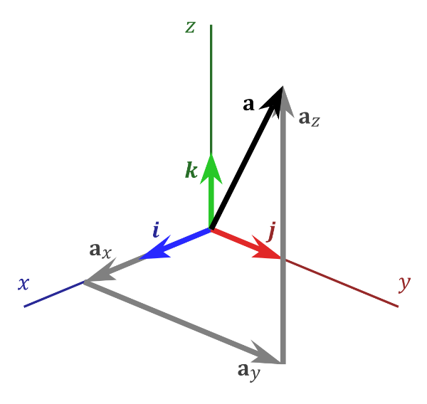
3D Vector Space by Wikipedia
In the image above, there are three axes, representing the x-axis (blue), y-axis (red), and z-axis (green). The vectors, i, j, and k, represent fundamental basis (or unit) vectors that can be combined, shrunk, or stretched to create any new vector such as vector a that has an x-component, y-component, and z-component.
Keep in mind that the image above is just one portrayal of 3D coordinate space. We can rotate the coordinate system in any way we want. As long as the three axes stay perpendicular (or orthogonal) to each other, then we can still keep all the vector arithmetic the same.
In Shadertoy, it’s very common for people to make a coordinate system where the x-axis is along the horizontal axis of the canvas, the y-axis is along the vertical axis of the canvas, and the z-axis is pointing toward you or away from you.
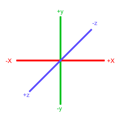
Notice the colors I’m using in the image above. The x-axis is colored red, the y-axis is colored green, and the z-axis is colored blue. This is intentional. As mentioned in Part 1 of this tutorial series, each axis corresponds to a color component:
vec3 someVariable = vec3(1, 2, 3);

someVariable.r == someVariable.x
someVariable.g == someVariable.y
someVariable.b == someVariable.z
In the image above, the z-axis is considered positive when it’s coming toward us and negative when it’s going away from us. This convention uses the right-hand rule. Using your right hand, you point your thumb to the right, index finger straight up, and your middle finger toward you such that each of your three fingers are pointing in perpendicular directions like a coordinate system. Each finger is pointing in the positive direction.
You’ll sometimes see this convention reversed along the z-axis when you’re reading other peoples’ code or reading other tutorials online. They might make the z-axis positive when it’s going away from you and negative when it’s coming toward you, but the x-axis and y-axis remain unchanged. This is known as the left-hand rule.
Ray Algorithms
Let’s finally talk about “ray algorithms” such as ray marching and ray tracing. Ray marching is the most common algorithm used to develop 3D scenes in Shadertoy, but you’ll see people leverage ray tracing or path tracing as well.
Both ray marching and ray tracing are algorithms used to draw 3D scenes on a 2D screen using rays. In real life, light sources such as the sun casts light rays in the form of photons in tons of different directions. When a photon hits an object, the energy is absorbed by the object’s crystal lattice of atoms, and another photon is released. Depending on the crystal structure of the material’s atomic lattice, photons can be emitted in a random direction (diffuse reflection), or at the same angle it entered the material (specular or mirror-like reflection).
I could talk about physics all day, but what we care about is how this relates to ray marching and ray tracing. Well, if we tried modelling a 3D scene starting at a light source and tracing it back to the camera, then we’d end up with a waste of computational resources. This “forward” simulation would lead to a ton of those rays never hitting our camera.
You’ll mostly see “backward” simulations where rays are shot out of a camera or “eye” instead. We work backwards! Light usually comes from a light source such as the sun, bounces off a bunch of objects, and hits our camera. Instead, our camera will shoot out rays in lots of different directions. These rays will bounce off objects in our scene, including a surface such as a floor, and some of them will hit a light source. If a ray bounces off a surface and hits an object instead of the light source, then it’s considered a “shadow ray” and tells us that we should draw a dark colored pixel to represent a shadow.

Ray tracing diagram by Wikipedia
In the image above, a camera shoots out rays in different directions. How many rays? One for each pixel in our canvas! We use each pixel in the Shadertoy canvas to generate a ray. Clever, right? Each pixel has a coordinate along the x-axis and y-axis, so why not use them to create rays with a z-component?
How many different directions will there be? One for each pixel as well! This is why it’s important to understand how rays work.
The ray origin for each ray fired from the camera will be the same as the position of our camera. Each ray will have a ray direction with an x-component, y-component, and z-component. Notice where the shadow rays originate from. The ray origin of the shadow rays will be equal to the point where the camera ray hit the surface. Every time the ray hits a surface, we can simulate a ray “bounce” or reflection by generating a new ray from that point. Keep this in mind later when we talk about illumination and shadows.
Difference between Ray Algorithms
Let’s discuss the difference between all the ray algorithms you might see out there online. These include ray casting, ray tracing, ray marching, and path tracing.
Ray Casting: A simpler form of ray tracing used in games like Wolfenstein 3D and Doom that fires a single ray and stops when it hits a target.
Ray Marching: A method of ray casting that uses signed distance fields (SDF) and commonly a sphere tracing algorithm that “marches” rays incrementally until it hits the closest object.
Ray Tracing: A more sophisticated version of ray casting that fires off rays, calculates ray-surface intersections, and recursively creates new rays upon each reflection.
Path Tracing: A type of ray tracing algorithm that shoots out hundreds or thousands of rays per pixel instead of just one. The rays are shot in random directions using the Monte Carlo method, and the final pixel color is determined from sampling the rays that make it to the light source.
If you ever see “Monte Carlo” anywhere, then that tells you right away you’ll probably be dealing with math related to probability and statistics.
You may also hear ray marching sometimes called “sphere tracing.” There is a good discussion about the difference between ray marching and sphere tracing on the computer graphics Stack Exchange. Basically, sphere tracing is one type of implementation of ray marching. Most of the ray marching techniques you see on Shadertoy will use sphere tracing, which is still a type of ray marching algorithm.
In case you’re wondering about spelling, I commonly see people use “raymarching” or “raytracing” as one word. When you’re googling for resources on these topics or using Cmd+F (or Ctrl+F) to search for any reference of ray marching or ray tracing, keep this in mind.
Ray Marching
For the rest of this article, I’ll be discussing how to use the ray marching algorithm in Shadertoy. There are many excellent online tutorials that teach about ray marching such as this tutorial by Jamie Wong. To help you visualize ray marching and why it’s sometimes called sphere tracing, this tutorial on Shadertoy is a valuable resource.
I’ll help break down the process of ray marching step by step, so you can start creating 3D scenes even with very little computer graphics experience.
We’ll create a simple camera so we can simulate a 3D scene in the Shadertoy canvas. Let’s imagine what our scene will look like first. We’ll start with the most basic object: a sphere.
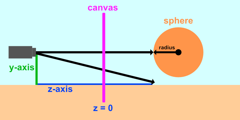
The image above shows a side view of the 3D scene we’ll be creating in Shadertoy. The x-axis is not pictured because it is pointing toward the viewer. Our camera will be treated as a point with a coordinate such as (0, 0, 5) which means it is 5 units away from the canvas along the z-axis. Like previous tutorials, we’ll remap the UV coordinates such that the origin is at the center of the canvas.
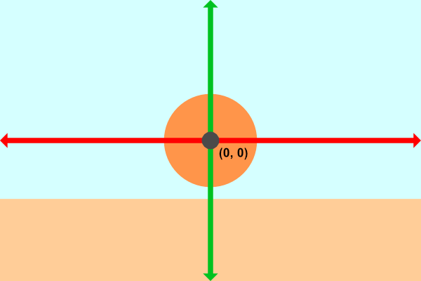
The image above represents the canvas from our perspective with an x-axis (red) and y-axis (green). We’ll be looking at the scene from the view of the camera. The ray shooting straight out of the camera through the origin of the canvas will hit our sphere. The diagonal ray fires from the camera at an angle and hits the ground (if it exists in the scene). If the ray doesn’t hit anything, then we’ll render a background color.
Now that we understand what we’re going to build, let’s start coding! Create a new Shadertoy shader and replace the contents with the following to setup our canvas:
 1void mainImage( out vec4 fragColor, in vec2 fragCoord )
 2{
 3  vec2 uv = fragCoord/iResolution.xy; // <0, 1>
 4  uv -= 0.5; // <-0.5,0.5>
 5  uv.x *= iResolution.x/iResolution.y; // fix aspect ratio
 6
 7  vec3 col = vec3(0);
 8
 9  // Output to screen
10  fragColor = vec4(col,1.0);
11}
To make our code cleaner, we can remap the UV coordinates in a single line instead of 3 lines. We’re used to what this code does by now!
1void mainImage( out vec4 fragColor, in vec2 fragCoord )
2{
3  vec2 uv = (fragCoord - .5 * iResolution.xy) / iResolution.y; // Condense 3 lines down to a single line!
4
5  vec3 col = vec3(0);
6
7  // Output to screen
8  fragColor = vec4(col,1.0);
9}
The ray origin, ro will be the position of our camera. We’ll set it 5 units behind the “canvas” we’re looking through.
1vec3 ro = vec3(0, 0, 5);Next, we’ll add a ray direction, rd, that will change based on the pixel coordinates. We’ll set the z-component to -1 so that each ray is fired toward our scene. We’ll then normalize the entire vector.
1vec3 rd = normalize(vec3(uv, -1));We’ll then setup a variable that returns the distance from the ray marching algorithm:
1float d = rayMarch(ro, rd, 0., 100.);Let’s create a function called rayMarch that implements the ray marching algorithm:
 1float rayMarch(vec3 ro, vec3 rd, float start, float end) {
 2  float depth = start;
 3
 4  for (int i = 0; i < 255; i++) {
 5    vec3 p = ro + depth * rd;
 6    float d = sdSphere(p, 1.);
 7    depth += d;
 8    if (d < 0.001 || depth > end) break;
 9  }
10
11  return depth;
12}
Let’s examine the ray marching algorithm a bit more closely. We start with a depth of zero and increment the depth gradually. Our test point is equal to the ray origin (our camera position) plus the depth times the ray direction. Remember, the ray marching algorithm will run for each pixel, and each pixel will determine a different ray direction.
We take the test point, p, and pass it to the sdSphere function which we will define as:
1float sdSphere(vec3 p, float r)
2{
3  return length(p) - r; // p is the test point and r is the radius of the sphere
4}
We’ll then increment the depth by the value of the distance returned by the sdSphere function. If the distance is within 0.001 units away from the sphere, then we consider this close enough to the sphere. This represents a precision. You can make this value lower if you want to make it more accurate.
If the distance is greater than a certain threshold, 100 in our case, then the ray has gone too far, and we should stop the ray marching loop. We don’t want the ray to continue off to infinity because that’s a waste of computational resources and would make a for loop run forever if the ray doesn’t hit anything.
Finally, we’ll add a color depending on whether the ray hit something or not:
1if (d > 100.0) {
2  col = vec3(0.6); // ray didn't hit anything
3} else {
4  col = vec3(0, 0, 1); // ray hit something
5}
Our finished code should look like the following:
 1float sdSphere(vec3 p, float r )
 2{
 3  return length(p) - r;
 4}
 5
 6float rayMarch(vec3 ro, vec3 rd, float start, float end) {
 7  float depth = start;
 8
 9  for (int i = 0; i < 255; i++) {
10    vec3 p = ro + depth * rd;
11    float d = sdSphere(p, 1.);
12    depth += d;
13    if (d < 0.001 || depth > end) break;
14  }
15
16  return depth;
17}
18
19void mainImage( out vec4 fragColor, in vec2 fragCoord )
20{
21  vec2 uv = (fragCoord-.5*iResolution.xy)/iResolution.y;
22
23  vec3 col = vec3(0);
24  vec3 ro = vec3(0, 0, 5); // ray origin that represents camera position
25  vec3 rd = normalize(vec3(uv, -1)); // ray direction
26
27  float d = rayMarch(ro, rd, 0., 100.); // distance to sphere
28
29  if (d > 100.0) {
30    col = vec3(0.6); // ray didn't hit anything
31  } else {
32    col = vec3(0, 0, 1); // ray hit something
33  }
34
35  // Output to screen
36  fragColor = vec4(col, 1.0);
37}
We seem to be reusing some numbers, so let’s set some constant global variables. In GLSL, we can use the const keyword to tell the compiler that we don’t plan on changing these variables:
1const int MAX_MARCHING_STEPS = 255;
2const float MIN_DIST = 0.0;
3const float MAX_DIST = 100.0;
4const float PRECISION = 0.001;
Alternatively, we can also use preprocessor directives. You may see people use preprocessor directives such as #define when they are defining constants. An advantage of using #define is that you’re able to use #ifdef to check if a variable is defined later in your code. There are differences between #define and const, so choose which one you prefer and which ones works best for your scenario.
If we rewrote the constant variables to use the #define preprocessor directive, then we’d have the following:
1#define MAX_MARCHING_STEPS 255
2#define MIN_DIST 0.0
3#define MAX_DIST 100.0
4#define PRECISION 0.001
Notice that we don’t use an equals sign or include a semicolon at the end of each line that uses a preprocessor directive.
The #define keyword lets us define both variables and functions, but I prefer to use const instead because of type safety.
Using these constant global variables, the code should now look like the following:
 1const int MAX_MARCHING_STEPS = 255;
 2const float MIN_DIST = 0.0;
 3const float MAX_DIST = 100.0;
 4const float PRECISION = 0.001;
 5
 6float sdSphere(vec3 p, float r )
 7{
 8  return length(p) - r;
 9}
10
11float rayMarch(vec3 ro, vec3 rd, float start, float end) {
12  float depth = start;
13
14  for (int i = 0; i < MAX_MARCHING_STEPS; i++) {
15    vec3 p = ro + depth * rd;
16    float d = sdSphere(p, 1.);
17    depth += d;
18    if (d < PRECISION || depth > end) break;
19  }
20
21  return depth;
22}
23
24void mainImage( out vec4 fragColor, in vec2 fragCoord )
25{
26  vec2 uv = (fragCoord-.5*iResolution.xy)/iResolution.y;
27
28  vec3 col = vec3(0);
29  vec3 ro = vec3(0, 0, 5); // ray origin that represents camera position
30  vec3 rd = normalize(vec3(uv, -1)); // ray direction
31
32  float d = rayMarch(ro, rd, MIN_DIST, MAX_DIST); // distance to sphere
33
34  if (d > MAX_DIST) {
35    col = vec3(0.6); // ray didn't hit anything
36  } else {
37    col = vec3(0, 0, 1); // ray hit something
38  }
39
40  // Output to screen
41  fragColor = vec4(col, 1.0);
42}
When we run the code, we should see an image of a sphere. It looks like a circle, but it’s definitely a sphere!
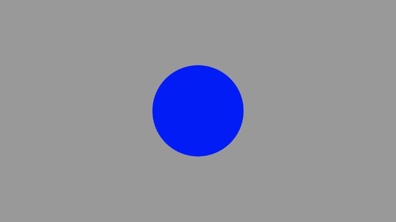
If we change the position of the camera, we can zoom in and out to prove that we’re looking at a 3D object. Increasing the distance between the camera and the virtual canvas in our scene from 5 to 3 should make the sphere appear bigger as if we stepped forward a bit.
1vec3 ro = vec3(0, 0, 3); // ray origin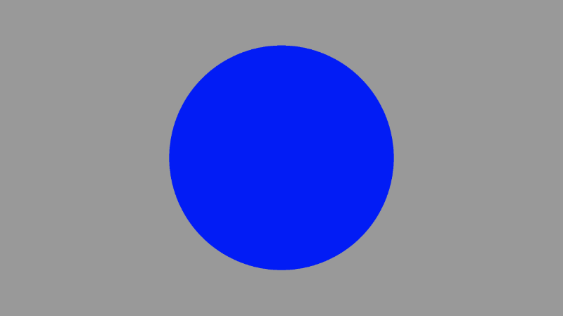
There is one issue though. Currently, the center of our sphere is at the coordinate, (0, 0, 0) which is different than the image I presented earlier. Our scene is setup that the camera is very close to the sphere.
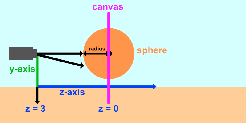
Let’s add an offset to the sphere similar to what we did with circles in Part 2 of my tutorial series.
1float sdSphere(vec3 p, float r )
2{
3  vec3 offset = vec3(0, 0, -2);
4  return length(p - offset) - r;
5}
This will push the sphere forward along the z-axis by two units. This should make the sphere appear smaller since it’s now farther away from the camera.
Lighting
To make this shape look more like a sphere, we need to add lighting. In the real world, light rays are scattered off objects in random directions.
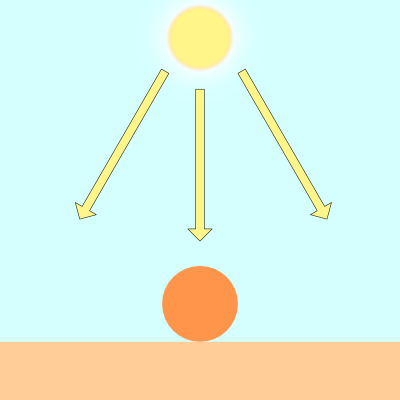
Objects appear differently depending on how much they are lit by a light source such as the sun.
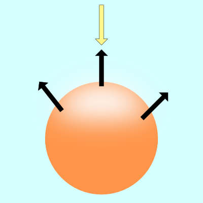
The black arrows in the image above represent a few surface normals of the sphere. If the surface normal points toward the light source, then that spot on the sphere appears brighter than the rest of the sphere. If the surface normal points completely away from the light source, then that part of the sphere will appear darker.
There are multiple types of lighting models used to simulate the real world. We’ll look into Lambert lighting to simulate diffuse reflection. This is commonly done by taking the dot product between the ray direction of a light source and the direction of a surface normal.
1vec3 diffuseReflection = dot(normal, lightDirection);A surface normal is commonly a normalized vector because we only care about the direction. To find this direction, we need to use the gradient. The surface normal will be equal to the gradient of a surface at a point on the surface.
Finding the gradient is like finding the slope of a line. You were probably told in school to memorize the phrase, “rise over run.” In 3D coordinate space, we can use the gradient to find the “direction” a point on the surface is pointing.
If you’ve taken a Calculus class, then you probably learned that the slope of a line is actually just an infinitesimally small difference between two points on the line.
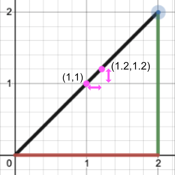
Let’s find the slope by performing “rise over run”:
Point 1 = (1, 1)
Point 2 = (1.2, 1.2)

Rise / Run = (y2 - y1) / (x2 - x1) = (1.2 - 1) / (1.2 - 1) = 0.2 / 0.2 = 1

Therefore, the slope is equal to one.
To find the gradient of a surface, we need two points. We’ll take a point on the surface of the sphere and subtract a small number from it to get the second point. That’ll let us perform a cheap trick to find the gradient. We can then use this gradient value as the surface normal.
Given a surface, f(x,y,z), the gradient along the surface will have the following equation:
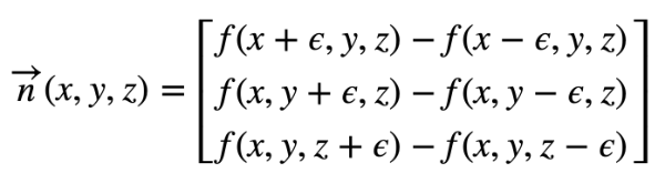
The curly symbol that looks like the letter, “e”, is the greek letter, epsilon. It will represent a tiny value next to a point on the surface of our sphere.
In GLSL, we’ll create a function called calcNormal that takes in a sample point we get back from the rayMarch function.
1vec3 calcNormal(vec3 p) {
2  float e = 0.0005; // epsilon
3  float r = 1.; // radius of sphere
4  return normalize(vec3(
5    sdSphere(vec3(p.x + e, p.y, p.z), r) - sdSphere(vec3(p.x - e, p.y, p.z), r),
6    sdSphere(vec3(p.x, p.y + e, p.z), r) - sdSphere(vec3(p.x, p.y - e, p.z), r),
7    sdSphere(vec3(p.x, p.y, p.z  + e), r) - sdSphere(vec3(p.x, p.y, p.z - e), r)
8  ));
9}
We can actually use Swizzling and vector arithmetic to create an alternative way of calculating a small gradient. Remember, our goal is to create a small gradient between two close points on the surface of the sphere (or approximately on the surface of the sphere). Although this new approach is not exactly the same as the code above, it works quite well for creating a small value that approximately points in the direction of the normal vector. That is to say, it works well at creating a gradient.
1vec3 calcNormal(vec3 p) {
2  vec2 e = vec2(1.0, -1.0) * 0.0005; // epsilon
3  float r = 1.; // radius of sphere
4  return normalize(
5    e.xyy * sdSphere(p + e.xyy, r) +
6    e.yyx * sdSphere(p + e.yyx, r) +
7    e.yxy * sdSphere(p + e.yxy, r) +
8    e.xxx * sdSphere(p + e.xxx, r));
9}
TIP
If you want to compare the differences between each
calcNormalimplementation, I have created a small JavaScript program that emulates some behavior of GLSL code.
The important thing to realize is that the calcNormal function returns a ray direction that represents the direction a point on the sphere is facing.
Next, we need to make a position for the light source. Think of it as a tiny point in 3D space.
1vec3 lightPosition = vec3(2, 2, 4);For now, we’ll have the light source always pointing toward the sphere. Therefore, the light ray direction will be the difference between the light position and a point we get back from the ray march loop.
1vec3 lightDirection = normalize(lightPosition - p);To find the amount of light hitting the surface of our sphere, we must calculate the dot product. In GLSL, we use the dot function to calculate this value.
1float dif = dot(normal, lightDirection); // dif = diffuse reflectionWhen we take the dot product between the normal and light direction vectors, we may end up with a negative value. To keep the value between zero and one so that we get a bigger range of values, we can use the clamp function.
1float dif = clamp(dot(normal, lightDirection), 0., 1.);Putting this altogether, we end up with the following code:
 1const int MAX_MARCHING_STEPS = 255;
 2const float MIN_DIST = 0.0;
 3const float MAX_DIST = 100.0;
 4const float PRECISION = 0.001;
 5
 6float sdSphere(vec3 p, float r )
 7{
 8  vec3 offset = vec3(0, 0, -2);
 9  return length(p - offset) - r;
10}
11
12float rayMarch(vec3 ro, vec3 rd, float start, float end) {
13  float depth = start;
14
15  for (int i = 0; i < MAX_MARCHING_STEPS; i++) {
16    vec3 p = ro + depth * rd;
17    float d = sdSphere(p, 1.);
18    depth += d;
19    if (d < PRECISION || depth > end) break;
20  }
21
22  return depth;
23}
24
25vec3 calcNormal(vec3 p) {
26    vec2 e = vec2(1.0, -1.0) * 0.0005; // epsilon
27    float r = 1.; // radius of sphere
28    return normalize(
29      e.xyy * sdSphere(p + e.xyy, r) +
30      e.yyx * sdSphere(p + e.yyx, r) +
31      e.yxy * sdSphere(p + e.yxy, r) +
32      e.xxx * sdSphere(p + e.xxx, r));
33}
34
35void mainImage( out vec4 fragColor, in vec2 fragCoord )
36{
37  vec2 uv = (fragCoord-.5*iResolution.xy)/iResolution.y;
38
39  vec3 col = vec3(0);
40  vec3 ro = vec3(0, 0, 3); // ray origin that represents camera position
41  vec3 rd = normalize(vec3(uv, -1)); // ray direction
42
43  float d = rayMarch(ro, rd, MIN_DIST, MAX_DIST); // distance to sphere
44
45  if (d > MAX_DIST) {
46    col = vec3(0.6); // ray didn't hit anything
47  } else {
48    vec3 p = ro + rd * d; // point on sphere we discovered from ray marching
49    vec3 normal = calcNormal(p);
50    vec3 lightPosition = vec3(2, 2, 4);
51    vec3 lightDirection = normalize(lightPosition - p);
52
53    // Calculate diffuse reflection by taking the dot product of
54    // the normal and the light direction.
55    float dif = clamp(dot(normal, lightDirection), 0., 1.);
56
57    col = vec3(dif);
58  }
59
60  // Output to screen
61  fragColor = vec4(col, 1.0);
62}
When you run this code, you should see a lit sphere! Now, you know I was telling the truth. Definitely looks like a sphere now! 😁
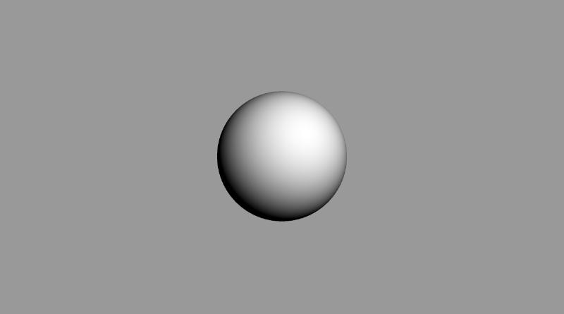
If you play around with the lightPosition variable, you should be able to move the light around in the 3D world coordinates. Moving the light around should affect how much shading the sphere gets. If you move the light source behind the camera, you should see the center of the sphere appear a lot brighter.
1vec3 lightPosition = vec3(2, 2, 7);You can also change the color of the sphere by multiplying the diffuse reflection value by a color vector:
1col = vec3(dif) * vec3(1, 0.58, 0.29);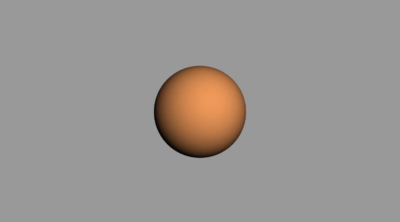
If you want to add a bit of ambient light color, you can adjust the clamped range, so the sphere doesn’t appear completely black in the shaded regions:
1float dif = clamp(dot(normal, lightDirection), 0.3, 1.);You can also change the background color and add a bit of this color to the color of the sphere, so it blends in well. Looks a bit like the reference image we saw earlier in this tutorial, huh? 😎
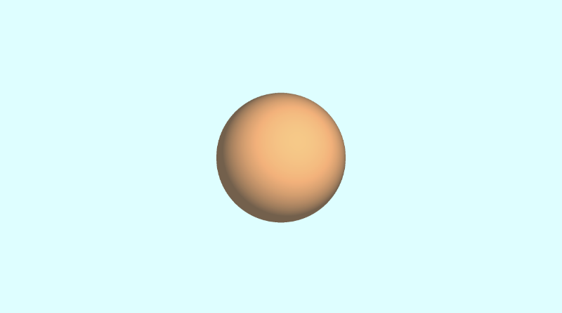
For reference, here is the completed code I used to create the image above.
 1const int MAX_MARCHING_STEPS = 255;
 2const float MIN_DIST = 0.0;
 3const float MAX_DIST = 100.0;
 4const float PRECISION = 0.001;
 5
 6float sdSphere(vec3 p, float r )
 7{
 8  vec3 offset = vec3(0, 0, -2);
 9  return length(p - offset) - r;
10}
11
12float rayMarch(vec3 ro, vec3 rd, float start, float end) {
13  float depth = start;
14
15  for (int i = 0; i < MAX_MARCHING_STEPS; i++) {
16    vec3 p = ro + depth * rd;
17    float d = sdSphere(p, 1.);
18    depth += d;
19    if (d < PRECISION || depth > end) break;
20  }
21
22  return depth;
23}
24
25vec3 calcNormal(vec3 p) {
26    vec2 e = vec2(1.0, -1.0) * 0.0005; // epsilon
27    float r = 1.; // radius of sphere
28    return normalize(
29      e.xyy * sdSphere(p + e.xyy, r) +
30      e.yyx * sdSphere(p + e.yyx, r) +
31      e.yxy * sdSphere(p + e.yxy, r) +
32      e.xxx * sdSphere(p + e.xxx, r));
33}
34
35void mainImage( out vec4 fragColor, in vec2 fragCoord )
36{
37  vec2 uv = (fragCoord-.5*iResolution.xy)/iResolution.y;
38  vec3 backgroundColor = vec3(0.835, 1, 1);
39
40  vec3 col = vec3(0);
41  vec3 ro = vec3(0, 0, 3); // ray origin that represents camera position
42  vec3 rd = normalize(vec3(uv, -1)); // ray direction
43
44  float d = rayMarch(ro, rd, MIN_DIST, MAX_DIST); // distance to sphere
45
46  if (d > MAX_DIST) {
47    col = backgroundColor; // ray didn't hit anything
48  } else {
49    vec3 p = ro + rd * d; // point on sphere we discovered from ray marching
50    vec3 normal = calcNormal(p);
51    vec3 lightPosition = vec3(2, 2, 7);
52    vec3 lightDirection = normalize(lightPosition - p);
53
54    // Calculate diffuse reflection by taking the dot product of
55    // the normal and the light direction.
56    float dif = clamp(dot(normal, lightDirection), 0.3, 1.);
57
58    // Multiply the diffuse reflection value by an orange color and add a bit
59    // of the background color to the sphere to blend it more with the background.
60    col = dif * vec3(1, 0.58, 0.29) + backgroundColor * .2;
61  }
62
63  // Output to screen
64  fragColor = vec4(col, 1.0);
65}
Conclusion
Phew! This article took about a weekend to write and get right, but I hope you had fun learning about ray marching! Please consider donating if you found this tutorial or any of my other past tutorials useful. We took the first step toward creating a 3D object using nothing but pixels on the screen and a clever algorithm. Til next time, happy coding!
Resources
- Difference between Ray Algorithms
- Ray Marching Tutorial by Jamie Wong
- Wikipedia: Ray Tracing
- Wikipedia: Lambertian Reflectance
- Wikipedia: Surface Normals
- Wolfram MathWorld: Gradient
- Wolfram MathWorld: Dot Product
- Shadertoy: Visual Ray Marching Tutorial
- Shadertoy: Super Simple Ray Marching Tutorial
- Shadertoy: Box and Balloon
- Shadertoy: Let’s Make a Ray Marcher
- Shadertoy: Ray Marching Primitives
- Shadertoy: Ray Marching Sample Code
- Shadertoy: Ray Marching Template
Tutorial Part 7 - Unique Colors and Multiple 3D Objects
转自:https://inspirnathan.com/posts/53-shadertoy-tutorial-part-7
Greetings, friends! Welcome to Part 7 of my Shadertoy tutorial series. Let’s add some color to our 3D scene and learn how to add multiple 3D objects to our scene such as a floor!
Drawing Multiple 3D Shapes
In the last tutorial, we learned how to draw a sphere using Shadertoy, but our scene was only set up to handle drawing one shape.
Let’s restructure our code so that a function called sdScene is responsible for returning the closest shape in our scene.
 1const int MAX_MARCHING_STEPS = 255;
 2const float MIN_DIST = 0.0;
 3const float MAX_DIST = 100.0;
 4const float PRECISION = 0.001;
 5
 6float sdSphere(vec3 p, float r )
 7{
 8  vec3 offset = vec3(0, 0, -2);
 9  return length(p - offset) - r;
10}
11
12float sdScene(vec3 p) {
13  return sdSphere(p, 1.);
14}
15
16float rayMarch(vec3 ro, vec3 rd, float start, float end) {
17  float depth = start;
18
19  for (int i = 0; i < MAX_MARCHING_STEPS; i++) {
20    vec3 p = ro + depth * rd;
21    float d = sdScene(p);
22    depth += d;
23    if (d < PRECISION || depth > end) break;
24  }
25
26  return depth;
27}
28
29vec3 calcNormal(in vec3 p) {
30    vec2 e = vec2(1.0, -1.0) * 0.0005; // epsilon
31    float r = 1.; // radius of sphere
32    return normalize(
33      e.xyy * sdScene(p + e.xyy) +
34      e.yyx * sdScene(p + e.yyx) +
35      e.yxy * sdScene(p + e.yxy) +
36      e.xxx * sdScene(p + e.xxx));
37}
38
39void mainImage( out vec4 fragColor, in vec2 fragCoord )
40{
41  vec2 uv = (fragCoord-.5*iResolution.xy)/iResolution.y;
42  vec3 backgroundColor = vec3(0.835, 1, 1);
43
44  vec3 col = vec3(0);
45  vec3 ro = vec3(0, 0, 3); // ray origin that represents camera position
46  vec3 rd = normalize(vec3(uv, -1)); // ray direction
47
48  float d = rayMarch(ro, rd, MIN_DIST, MAX_DIST); // distance to sphere
49
50  if (d > MAX_DIST) {
51    col = backgroundColor; // ray didn't hit anything
52  } else {
53    vec3 p = ro + rd * d; // point on sphere we discovered from ray marching
54    vec3 normal = calcNormal(p);
55    vec3 lightPosition = vec3(2, 2, 7);
56    vec3 lightDirection = normalize(lightPosition - p);
57
58    // Calculate diffuse reflection by taking the dot product of
59    // the normal and the light direction.
60    float dif = clamp(dot(normal, lightDirection), 0.3, 1.);
61
62    // Multiply the diffuse reflection value by an orange color and add a bit
63    // of the background color to the sphere to blend it more with the background.
64    col = dif * vec3(1, 0.58, 0.29) + backgroundColor * .2;
65  }
66
67  // Output to screen
68  fragColor = vec4(col, 1.0);
69}
Notice how every instance of sdSphere has been replaced with sdScene. If we want to add more objects to the scene, we can use the min function to get the nearest object in our scene.
1float sdScene(vec3 p) {
2  float sphereLeft = sdSphere(p, 1.);
3  float sphereRight = sdSphere(p, 1.);
4  return min(sphereLeft, sphereRight);
5}
Currently, the spheres are on top of each other though. Let’s add an offset parameter to our sdSphere function:
1float sdSphere(vec3 p, float r, vec3 offset )
2{
3  return length(p - offset) - r;
4}
Then, we can add offsets to each of our spheres:
1float sdScene(vec3 p) {
2  float sphereLeft = sdSphere(p, 1., vec3(-2.5, 0, -2));
3  float sphereRight = sdSphere(p, 1., vec3(2.5, 0, -2));
4  return min(sphereLeft, sphereRight);
5}
The completed code should look like the following:
 1const int MAX_MARCHING_STEPS = 255;
 2const float MIN_DIST = 0.0;
 3const float MAX_DIST = 100.0;
 4const float PRECISION = 0.001;
 5
 6float sdSphere(vec3 p, float r, vec3 offset )
 7{
 8  return length(p - offset) - r;
 9}
10
11float sdScene(vec3 p) {
12  float sphereLeft = sdSphere(p, 1., vec3(-2.5, 0, -2));
13  float sphereRight = sdSphere(p, 1., vec3(2.5, 0, -2));
14  return min(sphereLeft, sphereRight);
15}
16
17float rayMarch(vec3 ro, vec3 rd, float start, float end) {
18  float depth = start;
19
20  for (int i = 0; i < MAX_MARCHING_STEPS; i++) {
21    vec3 p = ro + depth * rd;
22    float d = sdScene(p);
23    depth += d;
24    if (d < PRECISION || depth > end) break;
25  }
26
27  return depth;
28}
29
30vec3 calcNormal(in vec3 p) {
31    vec2 e = vec2(1.0, -1.0) * 0.0005; // epsilon
32    float r = 1.; // radius of sphere
33    return normalize(
34      e.xyy * sdScene(p + e.xyy) +
35      e.yyx * sdScene(p + e.yyx) +
36      e.yxy * sdScene(p + e.yxy) +
37      e.xxx * sdScene(p + e.xxx));
38}
39
40void mainImage( out vec4 fragColor, in vec2 fragCoord )
41{
42  vec2 uv = (fragCoord-.5*iResolution.xy)/iResolution.y;
43  vec3 backgroundColor = vec3(0.835, 1, 1);
44
45  vec3 col = vec3(0);
46  vec3 ro = vec3(0, 0, 3); // ray origin that represents camera position
47  vec3 rd = normalize(vec3(uv, -1)); // ray direction
48
49  float d = rayMarch(ro, rd, MIN_DIST, MAX_DIST); // distance to sphere
50
51  if (d > MAX_DIST) {
52    col = backgroundColor; // ray didn't hit anything
53  } else {
54    vec3 p = ro + rd * d; // point on sphere we discovered from ray marching
55    vec3 normal = calcNormal(p);
56    vec3 lightPosition = vec3(2, 2, 7);
57    vec3 lightDirection = normalize(lightPosition - p);
58
59    // Calculate diffuse reflection by taking the dot product of
60    // the normal and the light direction.
61    float dif = clamp(dot(normal, lightDirection), 0.3, 1.);
62
63    // Multiply the diffuse reflection value by an orange color and add a bit
64    // of the background color to the sphere to blend it more with the background.
65    col = dif * vec3(1, 0.58, 0.29) + backgroundColor * .2;
66  }
67
68  // Output to screen
69  fragColor = vec4(col, 1.0);
70}
After running our code, we should see two orange spheres slightly apart from each other.
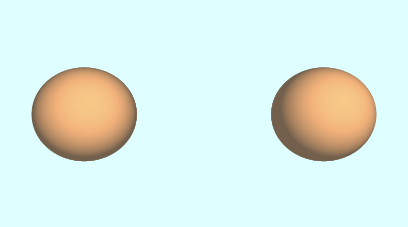
Adding a Floor
We can add a floor that will sit one unit below our spheres through the following function:
1float sdFloor(vec3 p) {
2  return p.y + 1.;
3}
By writing p.y + 1, it’s like saying p.y - (-1), which means we’re subtracting an offset from the floor and pushing it down one unit.
We can then add the floor to our sdScene function by using the min function again:
1float sdScene(vec3 p) {
2  float sphereLeft = sdSphere(p, 1., vec3(-2.5, 0, -2));
3  float sphereRight = sdSphere(p, 1., vec3(2.5, 0, -2));
4  float res = min(sphereLeft, sphereRight);
5  res = min(res, sdFloor(p));
6  return res;
7}
When we run our code, the floor looks brown because it’s using the same orange color as the spheres and not much light is hitting the surface of the floor.
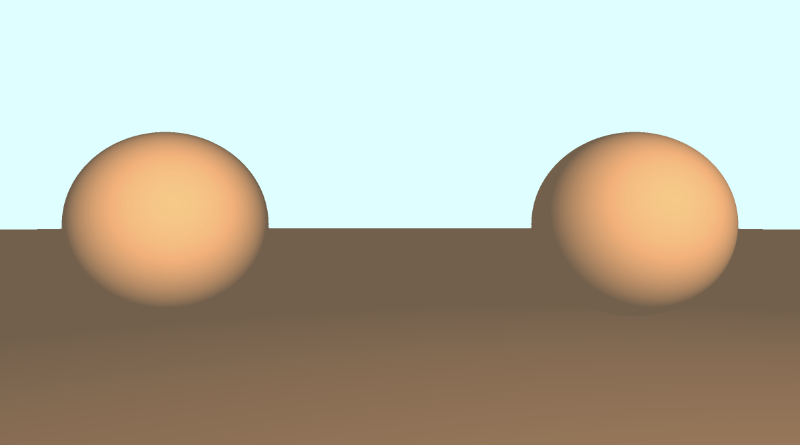
Adding Unique Colors - Method 1
There are multiple techniques people across Shadertoy use to add colors to 3D shapes. One way would be to modify our SDFs to return both the distance to our shape and a color. Therefore, we’d have to modify multiple places in our code to return a vec4 datatype instead of a float. The first value of the vec4 variable would hold the “signed distance” value we normally return from an SDF, and the last three values will hold our color value.
The finished code should look something like this:
 1const int MAX_MARCHING_STEPS = 255;
 2const float MIN_DIST = 0.0;
 3const float MAX_DIST = 100.0;
 4const float PRECISION = 0.001;
 5
 6vec4 sdSphere(vec3 p, float r, vec3 offset, vec3 col )
 7{
 8  float d = length(p - offset) - r;
 9  return vec4(d, col);
10}
11
12vec4 sdFloor(vec3 p, vec3 col) {
13  float d = p.y + 1.;
14  return vec4(d, col);
15}
16
17vec4 minWithColor(vec4 obj1, vec4 obj2) {
18  if (obj2.x < obj1.x) return obj2; // The x component of the object holds the "signed distance" value
19  return obj1;
20}
21
22vec4 sdScene(vec3 p) {
23  vec4 sphereLeft = sdSphere(p, 1., vec3(-2.5, 0, -2), vec3(0, .8, .8));
24  vec4 sphereRight = sdSphere(p, 1., vec3(2.5, 0, -2), vec3(1, 0.58, 0.29));
25  vec4 co = minWithColor(sphereLeft, sphereRight); // co = closest object containing "signed distance" and color
26  co = minWithColor(co, sdFloor(p, vec3(0, 1, 0)));
27  return co;
28}
29
30vec4 rayMarch(vec3 ro, vec3 rd, float start, float end) {
31  float depth = start;
32  vec4 co; // closest object
33
34  for (int i = 0; i < MAX_MARCHING_STEPS; i++) {
35    vec3 p = ro + depth * rd;
36    co = sdScene(p);
37    depth += co.x;
38    if (co.x < PRECISION || depth > end) break;
39  }
40
41  vec3 col = vec3(co.yzw);
42
43  return vec4(depth, col);
44}
45
46vec3 calcNormal(in vec3 p) {
47    vec2 e = vec2(1.0, -1.0) * 0.0005; // epsilon
48    return normalize(
49      e.xyy * sdScene(p + e.xyy).x +
50      e.yyx * sdScene(p + e.yyx).x +
51      e.yxy * sdScene(p + e.yxy).x +
52      e.xxx * sdScene(p + e.xxx).x);
53}
54
55void mainImage( out vec4 fragColor, in vec2 fragCoord )
56{
57  vec2 uv = (fragCoord-.5*iResolution.xy)/iResolution.y;
58  vec3 backgroundColor = vec3(0.835, 1, 1);
59
60  vec3 col = vec3(0);
61  vec3 ro = vec3(0, 0, 3); // ray origin that represents camera position
62  vec3 rd = normalize(vec3(uv, -1)); // ray direction
63
64  vec4 co = rayMarch(ro, rd, MIN_DIST, MAX_DIST); // closest object
65
66  if (co.x > MAX_DIST) {
67    col = backgroundColor; // ray didn't hit anything
68  } else {
69    vec3 p = ro + rd * co.x; // point on sphere or floor we discovered from ray marching
70    vec3 normal = calcNormal(p);
71    vec3 lightPosition = vec3(2, 2, 7);
72    vec3 lightDirection = normalize(lightPosition - p);
73
74    // Calculate diffuse reflection by taking the dot product of
75    // the normal and the light direction.
76    float dif = clamp(dot(normal, lightDirection), 0.3, 1.);
77
78    // Multiply the diffuse reflection value by an orange color and add a bit
79    // of the background color to the sphere to blend it more with the background.
80    col = dif * co.yzw + backgroundColor * .2;
81  }
82
83  // Output to screen
84  fragColor = vec4(col, 1.0);
85}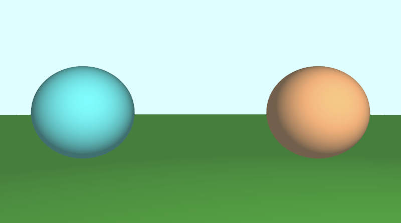
There are multiple places in our code where we had to make adjustments to satisfy the compiler. The first thing we changed was modifying the SDFs to return a vec4 value instead of a float.
 1vec4 sdSphere(vec3 p, float r, vec3 offset, vec3 col )
 2{
 3  float d = length(p - offset) - r;
 4  return vec4(d, col);
 5}
 6
 7vec4 sdFloor(vec3 p, vec3 col) {
 8  float d = p.y + 1.;
 9  return vec4(d, col);
10}
Both of these functions now accept a new parameter for color. However, that breaks the min function we were using inside the sdScene function, so we had to modify that too and create our own min function.
 1vec4 minWithColor(vec4 obj1, vec4 obj2) {
 2  if (obj2.x < obj1.x) return obj2;
 3  return obj1;
 4}
 5
 6vec4 sdScene(vec3 p) {
 7  vec4 sphereLeft = sdSphere(p, 1., vec3(-2.5, 0, -2), vec3(0, .8, .8));
 8  vec4 sphereRight = sdSphere(p, 1., vec3(2.5, 0, -2), vec3(1, 0.58, 0.29));
 9  vec4 co = minWithColor(sphereLeft, sphereRight); // co = closest object containing "signed distance" and color
10  co = minWithColor(co, sdFloor(p, vec3(0, 1, 0)));
11  return co;
12}
The minWithColor function performs the same operation as the min function, except it returns a vec4 that holds both the “signed distance” value and the color of the object that is closest during the ray marching loop. Speaking of ray marching, we had to modify our rayMarch function to satisfy the compiler as well.
 1vec4 rayMarch(vec3 ro, vec3 rd, float start, float end) {
 2  float depth = start;
 3  vec4 co; // closest object
 4
 5  for (int i = 0; i < MAX_MARCHING_STEPS; i++) {
 6    vec3 p = ro + depth * rd;
 7    co = sdScene(p);
 8    depth += co.x;
 9    if (co.x < PRECISION || depth > end) break;
10  }
11
12  vec3 col = vec3(co.yzw);
13
14  return vec4(depth, col);
15}
We also had to modify the calcNormal function to extract out the x-component of the object we get back from the sdScene function:
1vec3 calcNormal(in vec3 p) {
2    vec2 e = vec2(1.0, -1.0) * 0.0005; // epsilon
3    return normalize(
4      e.xyy * sdScene(p + e.xyy).x +
5      e.yyx * sdScene(p + e.yyx).x +
6      e.yxy * sdScene(p + e.yxy).x +
7      e.xxx * sdScene(p + e.xxx).x);
8}
Finally, we modified the mainImage function to use the changes as well.
 1void mainImage( out vec4 fragColor, in vec2 fragCoord )
 2{
 3  vec2 uv = (fragCoord-.5*iResolution.xy)/iResolution.y;
 4  vec3 backgroundColor = vec3(0.835, 1, 1);
 5
 6  vec3 col = vec3(0);
 7  vec3 ro = vec3(0, 0, 3); // ray origin that represents camera position
 8  vec3 rd = normalize(vec3(uv, -1)); // ray direction
 9
10  vec4 co = rayMarch(ro, rd, MIN_DIST, MAX_DIST); // closest object
11
12  if (co.x > MAX_DIST) {
13    col = backgroundColor; // ray didn't hit anything
14  } else {
15    vec3 p = ro + rd * co.x; // point on sphere or floor we discovered from ray marching
16    vec3 normal = calcNormal(p);
17    vec3 lightPosition = vec3(2, 2, 7);
18    vec3 lightDirection = normalize(lightPosition - p);
19
20    // Calculate diffuse reflection by taking the dot product of
21    // the normal and the light direction.
22    float dif = clamp(dot(normal, lightDirection), 0.3, 1.);
23
24    // Multiply the diffuse reflection value by an orange color and add a bit
25    // of the background color to the sphere to blend it more with the background.
26    col = dif * co.yzw + backgroundColor * .2;
27  }
28
29  // Output to screen
30  fragColor = vec4(col, 1.0);
31}
We extract out the “signed distance” value using col.x, and we get the color by using col.yzw.
Using this method allowed you to store values inside vec4 as if they were arrays in other languages. GLSL lets you use arrays as well, but they’re not as flexible as languages such as JavaScript. You have to know how many values are in the arrays, and you can only store the same type of values in the arrays.
Adding Unique Colors - Method 2
If using vec4 to store both the distance and color felt like a dirty solution, another option would be to use structs. Structs are a great way to organize your GLSL code. Structs are defined similar to C++ syntax. If you’re not familiar with C++ and are more familiar with JavaScript, then you can think of structs as like a combination of objects and classes. Let’s see what I mean by that.
A struct can have properties on them. Let’s create a struct called “Surface.”
1struct Surface {
2  float signedDistance;
3  vec3 color;
4};
You can create functions that return “Surface” structs, and you can create new instances of a struct:
1// This function's return value is of type "Surface"
2Surface sdSphere(vec3 p, float r, vec3 offset, vec3 col)
3{
4  float d = length(p - offset) - r;
5  return Surface(d, col); // We're initializing a new "Surface" struct here and then returning it
6}
You can access properties of the struct using the dot syntax:
1Surface minWithColor(Surface obj1, Surface obj2) {
2  if (obj2.sd < obj1.sd) return obj2; // The sd component of the struct holds the "signed distance" value
3  return obj1;
4}
With our new knowledge of structs, we can modify our code to use structs instead of using vec4.
 1const int MAX_MARCHING_STEPS = 255;
 2const float MIN_DIST = 0.0;
 3const float MAX_DIST = 100.0;
 4const float PRECISION = 0.001;
 5
 6struct Surface {
 7    float sd; // signed distance value
 8    vec3 col; // color
 9};
10
11Surface sdSphere(vec3 p, float r, vec3 offset, vec3 col)
12{
13  float d = length(p - offset) - r;
14  return Surface(d, col);
15}
16
17Surface sdFloor(vec3 p, vec3 col) {
18  float d = p.y + 1.;
19  return Surface(d, col);
20}
21
22Surface minWithColor(Surface obj1, Surface obj2) {
23  if (obj2.sd < obj1.sd) return obj2; // The sd component of the struct holds the "signed distance" value
24  return obj1;
25}
26
27Surface sdScene(vec3 p) {
28  Surface sphereLeft = sdSphere(p, 1., vec3(-2.5, 0, -2), vec3(0, .8, .8));
29  Surface sphereRight = sdSphere(p, 1., vec3(2.5, 0, -2), vec3(1, 0.58, 0.29));
30  Surface co = minWithColor(sphereLeft, sphereRight); // co = closest object containing "signed distance" and color
31  co = minWithColor(co, sdFloor(p, vec3(0, 1, 0)));
32  return co;
33}
34
35Surface rayMarch(vec3 ro, vec3 rd, float start, float end) {
36  float depth = start;
37  Surface co; // closest object
38
39  for (int i = 0; i < MAX_MARCHING_STEPS; i++) {
40    vec3 p = ro + depth * rd;
41    co = sdScene(p);
42    depth += co.sd;
43    if (co.sd < PRECISION || depth > end) break;
44  }
45
46  co.sd = depth;
47
48  return co;
49}
50
51vec3 calcNormal(in vec3 p) {
52    vec2 e = vec2(1.0, -1.0) * 0.0005; // epsilon
53    return normalize(
54      e.xyy * sdScene(p + e.xyy).sd +
55      e.yyx * sdScene(p + e.yyx).sd +
56      e.yxy * sdScene(p + e.yxy).sd +
57      e.xxx * sdScene(p + e.xxx).sd);
58}
59
60void mainImage( out vec4 fragColor, in vec2 fragCoord )
61{
62  vec2 uv = (fragCoord-.5*iResolution.xy)/iResolution.y;
63  vec3 backgroundColor = vec3(0.835, 1, 1);
64
65  vec3 col = vec3(0);
66  vec3 ro = vec3(0, 0, 3); // ray origin that represents camera position
67  vec3 rd = normalize(vec3(uv, -1)); // ray direction
68
69  Surface co = rayMarch(ro, rd, MIN_DIST, MAX_DIST); // closest object
70
71  if (co.sd > MAX_DIST) {
72    col = backgroundColor; // ray didn't hit anything
73  } else {
74    vec3 p = ro + rd * co.sd; // point on sphere or floor we discovered from ray marching
75    vec3 normal = calcNormal(p);
76    vec3 lightPosition = vec3(2, 2, 7);
77    vec3 lightDirection = normalize(lightPosition - p);
78
79    // Calculate diffuse reflection by taking the dot product of
80    // the normal and the light direction.
81    float dif = clamp(dot(normal, lightDirection), 0.3, 1.);
82
83    // Multiply the diffuse reflection value by an orange color and add a bit
84    // of the background color to the sphere to blend it more with the background.
85    col = dif * co.col + backgroundColor * .2;
86  }
87
88  // Output to screen
89  fragColor = vec4(col, 1.0);
90}
This code should behave the same as when we used vec4 earlier. In my opinion, structs are easier to reason about and look much cleaner. You’re also not limited to four values like you were in vec4 vectors. Choose whichever approach you prefer.
Making a Tiled Floor
If you want to make a fancy tiled floor, you can adjust the color of the floor like so:
1Surface sdScene(vec3 p) {
2  Surface sphereLeft = sdSphere(p, 1., vec3(-2.5, 0, -2), vec3(0, .8, .8));
3  Surface sphereRight = sdSphere(p, 1., vec3(2.5, 0, -2), vec3(1, 0.58, 0.29));
4  Surface co = minWithColor(sphereLeft, sphereRight);
5
6  vec3 floorColor = vec3(1. + 0.7*mod(floor(p.x) + floor(p.z), 2.0));
7  co = minWithColor(co, sdFloor(p, floorColor));
8  return co;
9}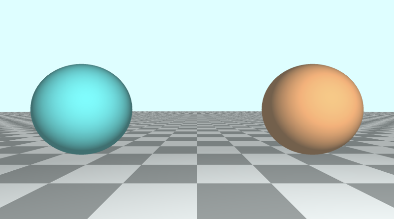
Tiled floors helps people visualize depth and make your 3D scenes stand out more. The mod function is commonly used to create checkered patterns or to divide a piece of the scene into repeatable chunks that can be colored or styled differently.
Adding Unique Colors - Method 3
When viewing shaders on Shadertoy, you may see code that uses identifiers or IDs to color each unique object in your scene. It’s common to see people use a map function instead of a sdScene function. You may also see a render function used to handle assigning colors to each object by looking at the ID of the closest object returned from the ray marching algorithm. Let’s see how the code looks using this more conventional approach.
 1const int MAX_MARCHING_STEPS = 255;
 2const float MIN_DIST = 0.0;
 3const float MAX_DIST = 100.0;
 4const float PRECISION = 0.001;
 5const vec3 COLOR_BACKGROUND = vec3(0.835, 1, 1);
 6
 7float sdSphere(vec3 p, float r)
 8{
 9  float d = length(p) - r;
10  return d;
11}
12
13float sdFloor(vec3 p) {
14  float d = p.y + 1.;
15  return d;
16}
17
18vec2 opU( vec2 d1, vec2 d2 )
19{
20  return (d1.x < d2.x) ? d1 : d2; // the x-component is the signed distance value
21}
22
23vec2 map(vec3 p) {
24  vec2 res = vec2(1e10, 0.); // ID = 0
25  vec2 flooring = vec2(sdFloor(p), 0.5); // ID = 0.5
26  vec2 sphereLeft = vec2(sdSphere(p - vec3(-2.5, 0, -2), 1.), 1.5); // ID = 1.5
27  vec2 sphereRight = vec2(sdSphere(p - vec3(2.5, 0, -2), 1.), 2.5); // ID = 2.5
28
29  res = opU(res, flooring);
30  res = opU(res, sphereLeft);
31  res = opU(res, sphereRight);
32  return res; // the y-component is the ID of the object hit by the ray
33}
34
35vec2 rayMarch(vec3 ro, vec3 rd) {
36  float depth = MIN_DIST;
37  vec2 res = vec2(0.0); // initialize result to zero for signed distance value and ID
38  float id = 0.;
39
40  for (int i = 0; i < MAX_MARCHING_STEPS; i++) {
41    vec3 p = ro + depth * rd;
42    res = map(p); // find resulting target hit by ray
43    depth += res.x;
44    id = res.y;
45    if (res.x < PRECISION || depth > MAX_DIST) break;
46  }
47
48  return vec2(depth, id);
49}
50
51vec3 calcNormal(in vec3 p) {
52    vec2 e = vec2(1.0, -1.0) * 0.0005; // epsilon
53    return normalize(
54      e.xyy * map(p + e.xyy).x +
55      e.yyx * map(p + e.yyx).x +
56      e.yxy * map(p + e.yxy).x +
57      e.xxx * map(p + e.xxx).x);
58}
59
60vec3 render(vec3 ro, vec3 rd) {
61    vec3 col = COLOR_BACKGROUND;
62
63    vec2 res = rayMarch(ro, rd);
64    float d = res.x; // signed distance value
65    if (d > MAX_DIST) return col; // render background color since ray hit nothing
66
67	float id = res.y; // id of object
68
69    vec3 p = ro + rd * d; // point on sphere or floor we discovered from ray marching
70    vec3 normal = calcNormal(p);
71    vec3 lightPosition = vec3(2, 2, 7);
72    vec3 lightDirection = normalize(lightPosition - p);
73
74    float dif = clamp(dot(normal, lightDirection), 0.3, 1.);
75
76    if (id > 0.) col = dif * vec3(1. + 0.7*mod(floor(p.x) + floor(p.z), 2.0));
77    if (id > 1.) col = dif * vec3(0, .8, .8);
78    if (id > 2.) col = dif * vec3(1, 0.58, 0.29);
79
80    col += COLOR_BACKGROUND * 0.2; // add a bit of the background color to blend objects more with the scene
81
82    return col;
83}
84
85void mainImage( out vec4 fragColor, in vec2 fragCoord )
86{
87  vec2 uv = (fragCoord-.5*iResolution.xy)/iResolution.y;
88
89  vec3 ro = vec3(0, 0, 3); // ray origin that represents camera position
90  vec3 rd = normalize(vec3(uv, -1)); // ray direction
91
92  vec3 col = render(ro, rd);
93
94  // Output to screen
95  fragColor = vec4(col, 1.0);
96}
You’ll notice that the minWithColor function is now called opU which stands for “operation, union” because it is a union operation that adds shapes to the scene. We’ll learn more about 3D SDF operations in Part 14 of my tutorial series. The opU function is comparing the signed distance values of two objects to see which object is closer to the ray during the ray marching algorithm.
The map function is used to add or “map” objects to our scene. We use a vec2 to store a value of the signed distance value in the x-component and an ID in the y-component. You’ll typically see a fractional value used for the ID. This is because we can check the ID in the render function by seeing if this fractional value is greater than a whole number. You may be wondering why we don’t use whole numbers for the ID and then use a == operator to check if the ID is equal to the ID of the closest object found from ray marching. This might work for you and your compiler, but it might not for everyone. Using fractional values and a greater than (>) check ensures the scene is guaranteed to render correctly. When using floats such as 1. or 2., you could find weird issues where id == 1. or id == 2. don’t behave as you’d expect. By checking if id > 1. or id > 2. when the ID is either 0.5 or 1.5, we can be sure that the code behaves predictably for everyone.
It’s important to understand this method for adding unique colors to the scene because you’ll likely see it used by many developers in the Shadertoy community.
Conclusion
In this article, we learned how to draw multiple 3D objects to the scene and give each of them a unique color. We learned three techniques for adding colors to each object in our scene, but there are definitely other approaches out there! Use whatever method works best for you. I find working with structs gives my code a more “structured” approach 🙂.
Resources
Tutorial Part 8 - 3D Rotation
转自:https://inspirnathan.com/posts/54-shadertoy-tutorial-part-8
Greetings, friends! Welcome to Part 8 of my Shadertoy tutorial series. In this tutorial, we’ll learn how to rotate 3D objects using transformation matrices.
Initial Setup
Let’s create a new shader and use the code from the end of Part 7 of this Shadertoy series. However, we’ll remove the spheres.
 1const int MAX_MARCHING_STEPS = 255;
 2const float MIN_DIST = 0.0;
 3const float MAX_DIST = 100.0;
 4const float PRECISION = 0.001;
 5
 6struct Surface {
 7    float sd; // signed distance value
 8    vec3 col; // color
 9};
10
11Surface sdFloor(vec3 p, vec3 col) {
12  float d = p.y + 1.;
13  return Surface(d, col);
14}
15
16Surface minWithColor(Surface obj1, Surface obj2) {
17  if (obj2.sd < obj1.sd) return obj2;
18  return obj1;
19}
20
21Surface sdScene(vec3 p) {
22  vec3 floorColor = vec3(1. + 0.7*mod(floor(p.x) + floor(p.z), 2.0));
23  Surface co = sdFloor(p, floorColor);
24  return co;
25}
26
27Surface rayMarch(vec3 ro, vec3 rd, float start, float end) {
28  float depth = start;
29  Surface co; // closest object
30
31  for (int i = 0; i < MAX_MARCHING_STEPS; i++) {
32    vec3 p = ro + depth * rd;
33    co = sdScene(p);
34    depth += co.sd;
35    if (co.sd < PRECISION || depth > end) break;
36  }
37
38  co.sd = depth;
39
40  return co;
41}
42
43vec3 calcNormal(in vec3 p) {
44    vec2 e = vec2(1.0, -1.0) * 0.0005; // epsilon
45    return normalize(
46      e.xyy * sdScene(p + e.xyy).sd +
47      e.yyx * sdScene(p + e.yyx).sd +
48      e.yxy * sdScene(p + e.yxy).sd +
49      e.xxx * sdScene(p + e.xxx).sd);
50}
51
52void mainImage( out vec4 fragColor, in vec2 fragCoord )
53{
54  vec2 uv = (fragCoord-.5*iResolution.xy)/iResolution.y;
55  vec3 backgroundColor = vec3(0.835, 1, 1);
56
57  vec3 col = vec3(0);
58  vec3 ro = vec3(0, 0, 3); // ray origin that represents camera position
59  vec3 rd = normalize(vec3(uv, -1)); // ray direction
60
61  Surface co = rayMarch(ro, rd, MIN_DIST, MAX_DIST); // closest object
62
63  if (co.sd > MAX_DIST) {
64    col = backgroundColor; // ray didn't hit anything
65  } else {
66    vec3 p = ro + rd * co.sd; // point on cube or floor we discovered from ray marching
67    vec3 normal = calcNormal(p);
68    vec3 lightPosition = vec3(2, 2, 7);
69    vec3 lightDirection = normalize(lightPosition - p);
70
71    float dif = clamp(dot(normal, lightDirection), 0.3, 1.); // diffuse reflection
72
73    col = dif * co.col + backgroundColor * .2; // Add a bit of background color to the diffuse color
74  }
75
76  // Output to screen
77  fragColor = vec4(col, 1.0);
78}
Once the code is run, you should see a tiled floor and light blue background color.
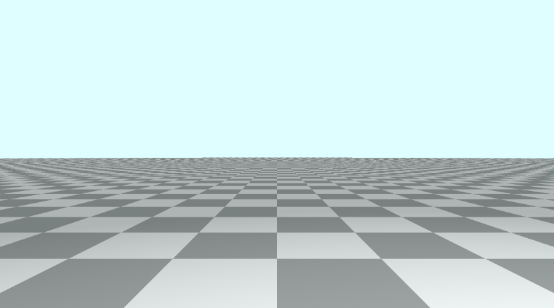
Adding a Cube
Next, we’ll add a cube by leveraging a list of 3D SDFs from Inigo Quilez’s website. Under the “Primitives” section, you will find an SDF labelled “Box - exact” which we will use to render a cube.
1float sdBox( vec3 p, vec3 b )
2{
3  vec3 q = abs(p) - b;
4  return length(max(q,0.0)) + min(max(q.x,max(q.y,q.z)),0.0);
5}
To make this compatible with the code we learned in the previous tutorial and to add a unique color to the object, we need to return a value of type Surface instead of a float. We’ll also add two parameters to the function: offset and color.
1Surface sdBox( vec3 p, vec3 b, vec3 offset, vec3 col)
2{
3  p = p - offset;
4  vec3 q = abs(p) - b;
5  float d = length(max(q,0.0)) + min(max(q.x,max(q.y,q.z)),0.0);
6  return Surface(d, col);
7}
The first parameter, p, is the sample point, and the second parameter, b, is a vec3 variable that represents the boundaries of the box. Use the x,y, and z components to control the width, height, and depth of the box. If we make all three the same value, then we end up with a cube.
Let’s insert a cube into our 3D scene:
1Surface sdScene(vec3 p) {
2  vec3 floorColor = vec3(1. + 0.7*mod(floor(p.x) + floor(p.z), 2.0));
3  Surface co = sdFloor(p, floorColor);
4  co = minWithColor(co, sdBox(p, vec3(1), vec3(0, 0.5, -4), vec3(1, 0, 0)));
5  return co;
6}
This cube will be 1x1x1 in dimensions, have the position, (0, 0.5, -4), and have the color, red.
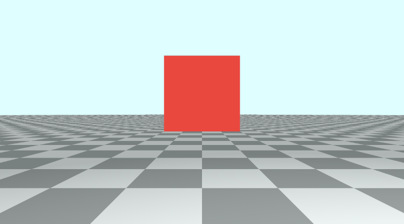
Rotation Matrices
In linear algebra, transformation matrices are used to perform a variety of operations on 2D and 3D shapes: stretching, squeezing, rotation, shearing, and reflection. Each matrix represents an operation.
By multiplying points on a graph (or sample points in our GLSL code) by a transformation matrix, we can perform any of these operations. We can also multiply any of these transformation matrices together to create new transformation matrices that perform more than one operation.
Since matrix multiplication is non-commutative, the order by which we multiply the matrices together matters. If you rotate a shape and then shear it, you’ll end up with a different result than if you sheared it first and then rotated it. Similarly, if you rotate a shape across the x-axis first and then the z-axis, you may end up with a different result had you reversed the order of these operations instead.
A rotation matrix is a type of transformation matrix. Let’s take a look at the rotation matrices we’ll be using in this tutorial.
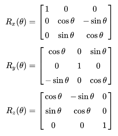
Rotation Matrices by Wikipedia
In the image above, we have three rotation matrices, one for each axis in 3D. These will let us spin a shape around an axis as if it were a gymnast swinging around a bar or pole.
At the top of our code, let’s add functions for rotation matrices across each axis. We’ll also add a function that returns an identity matrix so that we can choose not to perform any sort of transformation.
 1// Rotation matrix around the X axis.
 2mat3 rotateX(float theta) {
 3    float c = cos(theta);
 4    float s = sin(theta);
 5    return mat3(
 6        vec3(1, 0, 0),
 7        vec3(0, c, -s),
 8        vec3(0, s, c)
 9    );
10}
11
12// Rotation matrix around the Y axis.
13mat3 rotateY(float theta) {
14    float c = cos(theta);
15    float s = sin(theta);
16    return mat3(
17        vec3(c, 0, s),
18        vec3(0, 1, 0),
19        vec3(-s, 0, c)
20    );
21}
22
23// Rotation matrix around the Z axis.
24mat3 rotateZ(float theta) {
25    float c = cos(theta);
26    float s = sin(theta);
27    return mat3(
28        vec3(c, -s, 0),
29        vec3(s, c, 0),
30        vec3(0, 0, 1)
31    );
32}
33
34// Identity matrix.
35mat3 identity() {
36    return mat3(
37        vec3(1, 0, 0),
38        vec3(0, 1, 0),
39        vec3(0, 0, 1)
40    );
41}
We now need to adjust the sdBox function to accept matrix transformations as another parameter. We will multiply the sample point by the rotation matrix. This transformation will be applied after the sample point is moved to a certain world coordinate defined by the offset.
1Surface sdBox( vec3 p, vec3 b, vec3 offset, vec3 col, mat3 transform)
2{
3  p = (p - offset) * transform;
4  vec3 q = abs(p) - b;
5  float d = length(max(q,0.0)) + min(max(q.x,max(q.y,q.z)),0.0);
6  return Surface(d, col);
7}
We then need to modify the sdScene function to insert a new parameter inside the call to the sdBox function:
1Surface sdScene(vec3 p) {
2  vec3 floorColor = vec3(1. + 0.7*mod(floor(p.x) + floor(p.z), 2.0));
3  Surface co = sdFloor(p, floorColor);
4  co = minWithColor(co, sdBox(p, vec3(1), vec3(0, 0.5, -4), vec3(1, 0, 0), rotateX(iTime)));
5  return co;
6}
We can use between rotateX, rotateY, and rotateZ to rotate the cube across the x-axis, y-axis, and z-axis, respectively. The angle will be set to iTime, so we can see animate the cube rotation with time. The cube’s pivot point will be its own center.
Here’s an example of rotating the cube across the x-axis using rotateX(iTime) in the call to the sdBox function.
Here’s an example of rotating the cube across the y-axis using rotateY(iTime) in the call to the sdBox function.
Here’s an example of rotating the cube across the z-axis using rotateZ(iTime) in the call to the sdBox function.
To prevent any sort of rotation, we can call the identity function:
1Surface sdScene(vec3 p) {
2  vec3 floorColor = vec3(1. + 0.7*mod(floor(p.x) + floor(p.z), 2.0));
3  Surface co = sdFloor(p, floorColor);
4  co = minWithColor(co, sdBox(p, vec3(1), vec3(0, 0.5, -4), vec3(1, 0, 0), identity())); // By using the identity matrix, the cube's orientation remains the same
5  return co;
6}
You can also combine individual matrix transforms by multiplying them together. This will cause the cube to rotate across all of the axes simultaneously.
 1Surface sdScene(vec3 p) {
 2  vec3 floorColor = vec3(1. + 0.7*mod(floor(p.x) + floor(p.z), 2.0));
 3  Surface co = sdFloor(p, floorColor);
 4  co = minWithColor(co, sdBox(
 5      p,
 6      vec3(1),
 7      vec3(0, 0.5, -4),
 8      vec3(1, 0, 0),
 9      rotateX(iTime) * rotateY(iTime) * rotateZ(iTime) // Combine rotation matrices
10  ));
11  return co;
12}
You can find an example of the completed code below:
  1// Rotation matrix around the X axis.
  2mat3 rotateX(float theta) {
  3    float c = cos(theta);
  4    float s = sin(theta);
  5    return mat3(
  6        vec3(1, 0, 0),
  7        vec3(0, c, -s),
  8        vec3(0, s, c)
  9    );
 10}
 11
 12// Rotation matrix around the Y axis.
 13mat3 rotateY(float theta) {
 14    float c = cos(theta);
 15    float s = sin(theta);
 16    return mat3(
 17        vec3(c, 0, s),
 18        vec3(0, 1, 0),
 19        vec3(-s, 0, c)
 20    );
 21}
 22
 23// Rotation matrix around the Z axis.
 24mat3 rotateZ(float theta) {
 25    float c = cos(theta);
 26    float s = sin(theta);
 27    return mat3(
 28        vec3(c, -s, 0),
 29        vec3(s, c, 0),
 30        vec3(0, 0, 1)
 31    );
 32}
 33
 34// Identity matrix.
 35mat3 identity() {
 36    return mat3(
 37        vec3(1, 0, 0),
 38        vec3(0, 1, 0),
 39        vec3(0, 0, 1)
 40    );
 41}
 42
 43const int MAX_MARCHING_STEPS = 255;
 44const float MIN_DIST = 0.0;
 45const float MAX_DIST = 100.0;
 46const float PRECISION = 0.001;
 47
 48struct Surface {
 49    float sd; // signed distance value
 50    vec3 col; // color
 51};
 52
 53Surface sdBox( vec3 p, vec3 b, vec3 offset, vec3 col, mat3 transform)
 54{
 55  p = (p - offset) * transform;
 56  vec3 q = abs(p) - b;
 57  float d = length(max(q,0.0)) + min(max(q.x,max(q.y,q.z)),0.0);
 58  return Surface(d, col);
 59}
 60
 61Surface sdFloor(vec3 p, vec3 col) {
 62  float d = p.y + 1.;
 63  return Surface(d, col);
 64}
 65
 66Surface minWithColor(Surface obj1, Surface obj2) {
 67  if (obj2.sd < obj1.sd) return obj2;
 68  return obj1;
 69}
 70
 71Surface sdScene(vec3 p) {
 72  vec3 floorColor = vec3(1. + 0.7*mod(floor(p.x) + floor(p.z), 2.0));
 73  Surface co = sdFloor(p, floorColor);
 74  co = minWithColor(co, sdBox(
 75      p,
 76      vec3(1),
 77      vec3(0, 0.5, -4),
 78      vec3(1, 0, 0),
 79      rotateX(iTime)*rotateY(iTime)*rotateZ(iTime) // Combine rotation matrices
 80  ));
 81  return co;
 82}
 83
 84Surface rayMarch(vec3 ro, vec3 rd, float start, float end) {
 85  float depth = start;
 86  Surface co; // closest object
 87
 88  for (int i = 0; i < MAX_MARCHING_STEPS; i++) {
 89    vec3 p = ro + depth * rd;
 90    co = sdScene(p);
 91    depth += co.sd;
 92    if (co.sd < PRECISION || depth > end) break;
 93  }
 94
 95  co.sd = depth;
 96
 97  return co;
 98}
 99
100vec3 calcNormal(in vec3 p) {
101    vec2 e = vec2(1.0, -1.0) * 0.0005; // epsilon
102    return normalize(
103      e.xyy * sdScene(p + e.xyy).sd +
104      e.yyx * sdScene(p + e.yyx).sd +
105      e.yxy * sdScene(p + e.yxy).sd +
106      e.xxx * sdScene(p + e.xxx).sd);
107}
108
109void mainImage( out vec4 fragColor, in vec2 fragCoord )
110{
111  vec2 uv = (fragCoord-.5*iResolution.xy)/iResolution.y;
112  vec3 backgroundColor = vec3(0.835, 1, 1);
113
114  vec3 col = vec3(0);
115  vec3 ro = vec3(0, 0, 3); // ray origin that represents camera position
116  vec3 rd = normalize(vec3(uv, -1)); // ray direction
117
118  Surface co = rayMarch(ro, rd, MIN_DIST, MAX_DIST); // closest object
119
120  if (co.sd > MAX_DIST) {
121    col = backgroundColor; // ray didn't hit anything
122  } else {
123    vec3 p = ro + rd * co.sd; // point on cube or floor we discovered from ray marching
124    vec3 normal = calcNormal(p);
125    vec3 lightPosition = vec3(2, 2, 7);
126    vec3 lightDirection = normalize(lightPosition - p);
127
128    float dif = clamp(dot(normal, lightDirection), 0.3, 1.); // diffuse reflection
129
130    col = dif * co.col + backgroundColor * .2; // Add a bit of background color to the diffuse color
131  }
132
133  // Output to screen
134  fragColor = vec4(col, 1.0);
135}
Rotation around a Pivot Point
If we wanted to make it seem like the cube is rotating around an external pivot point that is not the cube’s center, then we’d have to modify the sdBox function to move the cube a certain distance after the transformation.
1Surface sdBox( vec3 p, vec3 b, vec3 offset, vec3 col, mat3 transform)
2{
3  p = (p - offset) * transform - vec3(3, 0, 0); // Move the cube as it is rotating
4  vec3 q = abs(p) - b;
5  float d = length(max(q,0.0)) + min(max(q.x,max(q.y,q.z)),0.0);
6  return Surface(d, col);
7}
If we use rotateY(iTime) inside the sdScene function, the cube appears to be rotating around the y-axis along a pivot point that is a certain distance away from the cube. In this example, we use vec3(3, 0, 0) to keep the cube 3 units away while it is rotating around the pivot point located at (0, 0.5, -4), which is the offset we assigned to sdBox inside the sdScene function.
Here is the full code used to create the image above:
  1// Rotation matrix around the X axis.
  2mat3 rotateX(float theta) {
  3    float c = cos(theta);
  4    float s = sin(theta);
  5    return mat3(
  6        vec3(1, 0, 0),
  7        vec3(0, c, -s),
  8        vec3(0, s, c)
  9    );
 10}
 11
 12// Rotation matrix around the Y axis.
 13mat3 rotateY(float theta) {
 14    float c = cos(theta);
 15    float s = sin(theta);
 16    return mat3(
 17        vec3(c, 0, s),
 18        vec3(0, 1, 0),
 19        vec3(-s, 0, c)
 20    );
 21}
 22
 23// Rotation matrix around the Z axis.
 24mat3 rotateZ(float theta) {
 25    float c = cos(theta);
 26    float s = sin(theta);
 27    return mat3(
 28        vec3(c, -s, 0),
 29        vec3(s, c, 0),
 30        vec3(0, 0, 1)
 31    );
 32}
 33
 34// Identity matrix.
 35mat3 identity() {
 36    return mat3(
 37        vec3(1, 0, 0),
 38        vec3(0, 1, 0),
 39        vec3(0, 0, 1)
 40    );
 41}
 42
 43const int MAX_MARCHING_STEPS = 255;
 44const float MIN_DIST = 0.0;
 45const float MAX_DIST = 100.0;
 46const float PRECISION = 0.001;
 47
 48struct Surface {
 49    float sd; // signed distance value
 50    vec3 col; // color
 51};
 52
 53Surface sdBox( vec3 p, vec3 b, vec3 offset, vec3 col, mat3 transform)
 54{
 55  p = (p - offset) * transform - vec3(3, 0, 0); // Move the cube as it is rotating
 56  vec3 q = abs(p) - b;
 57  float d = length(max(q,0.0)) + min(max(q.x,max(q.y,q.z)),0.0);
 58  return Surface(d, col);
 59}
 60
 61Surface sdFloor(vec3 p, vec3 col) {
 62  float d = p.y + 1.;
 63  return Surface(d, col);
 64}
 65
 66Surface minWithColor(Surface obj1, Surface obj2) {
 67  if (obj2.sd < obj1.sd) return obj2;
 68  return obj1;
 69}
 70
 71Surface sdScene(vec3 p) {
 72  vec3 floorColor = vec3(1. + 0.7*mod(floor(p.x) + floor(p.z), 2.0));
 73  Surface co = sdFloor(p, floorColor);
 74  co = minWithColor(co, sdBox(p, vec3(1), vec3(0, 0.5, -4), vec3(1, 0, 0), rotateY(iTime)));
 75  return co;
 76}
 77
 78Surface rayMarch(vec3 ro, vec3 rd, float start, float end) {
 79  float depth = start;
 80  Surface co; // closest object
 81
 82  for (int i = 0; i < MAX_MARCHING_STEPS; i++) {
 83    vec3 p = ro + depth * rd;
 84    co = sdScene(p);
 85    depth += co.sd;
 86    if (co.sd < PRECISION || depth > end) break;
 87  }
 88
 89  co.sd = depth;
 90
 91  return co;
 92}
 93
 94vec3 calcNormal(in vec3 p) {
 95    vec2 e = vec2(1.0, -1.0) * 0.0005; // epsilon
 96    return normalize(
 97      e.xyy * sdScene(p + e.xyy).sd +
 98      e.yyx * sdScene(p + e.yyx).sd +
 99      e.yxy * sdScene(p + e.yxy).sd +
100      e.xxx * sdScene(p + e.xxx).sd);
101}
102
103void mainImage( out vec4 fragColor, in vec2 fragCoord )
104{
105  vec2 uv = (fragCoord-.5*iResolution.xy)/iResolution.y;
106  vec3 backgroundColor = vec3(0.835, 1, 1);
107
108  vec3 col = vec3(0);
109  vec3 ro = vec3(0, 0, 3); // ray origin that represents camera position
110  vec3 rd = normalize(vec3(uv, -1)); // ray direction
111
112  Surface co = rayMarch(ro, rd, MIN_DIST, MAX_DIST); // closest object
113
114  if (co.sd > MAX_DIST) {
115    col = backgroundColor; // ray didn't hit anything
116  } else {
117    vec3 p = ro + rd * co.sd; // point on cube or floor we discovered from ray marching
118    vec3 normal = calcNormal(p);
119    vec3 lightPosition = vec3(2, 2, 7);
120    vec3 lightDirection = normalize(lightPosition - p);
121
122    float dif = clamp(dot(normal, lightDirection), 0.3, 1.); // diffuse reflection
123
124    col = dif * co.col + backgroundColor * .2; // Add a bit of background color to the diffuse color
125  }
126
127  // Output to screen
128  fragColor = vec4(col, 1.0);
129}
Conclusion
In this tutorial, we learned how to rotate our cube across each axis in 3D space. We also learned how to rotate cubes around an external pivot point to make it look like they’re orbiting around a point in space. What you learned today can be applied to all other 3D objects as well. We chose a cube instead of a sphere because it’s easier to check if our rotation matrices work against cubes rather than spheres 🙂.
Resources
Tutorial Part 9 - Camera Movement
转自:https://inspirnathan.com/posts/55-shadertoy-tutorial-part-9
Greetings, friends! It’s April Fools’ day! I hope you don’t fall for many pranks today! 😂 Welcome to Part 9 of my Shadertoy tutorial series. In this tutorial, we’ll learn how move the camera around the scene.
Initial Setup
Let’s create a new shader and add the following boilerplate code.
  1// Rotation matrix around the X axis.
  2mat3 rotateX(float theta) {
  3    float c = cos(theta);
  4    float s = sin(theta);
  5    return mat3(
  6        vec3(1, 0, 0),
  7        vec3(0, c, -s),
  8        vec3(0, s, c)
  9    );
 10}
 11
 12// Rotation matrix around the Y axis.
 13mat3 rotateY(float theta) {
 14    float c = cos(theta);
 15    float s = sin(theta);
 16    return mat3(
 17        vec3(c, 0, s),
 18        vec3(0, 1, 0),
 19        vec3(-s, 0, c)
 20    );
 21}
 22
 23// Rotation matrix around the Z axis.
 24mat3 rotateZ(float theta) {
 25    float c = cos(theta);
 26    float s = sin(theta);
 27    return mat3(
 28        vec3(c, -s, 0),
 29        vec3(s, c, 0),
 30        vec3(0, 0, 1)
 31    );
 32}
 33
 34// Identity matrix.
 35mat3 identity() {
 36    return mat3(
 37        vec3(1, 0, 0),
 38        vec3(0, 1, 0),
 39        vec3(0, 0, 1)
 40    );
 41}
 42
 43const int MAX_MARCHING_STEPS = 255;
 44const float MIN_DIST = 0.0;
 45const float MAX_DIST = 100.0;
 46const float PRECISION = 0.001;
 47
 48struct Surface {
 49    float sd; // signed distance value
 50    vec3 col; // color
 51};
 52
 53Surface sdBox( vec3 p, vec3 b, vec3 offset, vec3 col, mat3 transform)
 54{
 55  p = (p - offset) * transform; // apply transformation matrix
 56  vec3 q = abs(p) - b;
 57  float d = length(max(q,0.0)) + min(max(q.x,max(q.y,q.z)),0.0);
 58  return Surface(d, col);
 59}
 60
 61Surface sdFloor(vec3 p, vec3 col) {
 62  float d = p.y + 1.;
 63  return Surface(d, col);
 64}
 65
 66Surface minWithColor(Surface obj1, Surface obj2) {
 67  if (obj2.sd < obj1.sd) return obj2;
 68  return obj1;
 69}
 70
 71Surface sdScene(vec3 p) {
 72  vec3 floorColor = vec3(1. + 0.7*mod(floor(p.x) + floor(p.z), 2.0));
 73  Surface co = sdFloor(p, floorColor);
 74  co = minWithColor(co, sdBox(p, vec3(1), vec3(0, 0.5, -4), vec3(1, 0, 0), identity()));
 75  return co;
 76}
 77
 78Surface rayMarch(vec3 ro, vec3 rd, float start, float end) {
 79  float depth = start;
 80  Surface co; // closest object
 81
 82  for (int i = 0; i < MAX_MARCHING_STEPS; i++) {
 83    vec3 p = ro + depth * rd;
 84    co = sdScene(p);
 85    depth += co.sd;
 86    if (co.sd < PRECISION || depth > end) break;
 87  }
 88
 89  co.sd = depth;
 90
 91  return co;
 92}
 93
 94vec3 calcNormal(in vec3 p) {
 95    vec2 e = vec2(1.0, -1.0) * 0.0005; // epsilon
 96    return normalize(
 97      e.xyy * sdScene(p + e.xyy).sd +
 98      e.yyx * sdScene(p + e.yyx).sd +
 99      e.yxy * sdScene(p + e.yxy).sd +
100      e.xxx * sdScene(p + e.xxx).sd);
101}
102
103void mainImage( out vec4 fragColor, in vec2 fragCoord )
104{
105  vec2 uv = (fragCoord-.5*iResolution.xy)/iResolution.y;
106  vec3 backgroundColor = vec3(0.835, 1, 1);
107
108  vec3 col = vec3(0);
109  vec3 ro = vec3(0, 0, 3); // ray origin that represents camera position
110  vec3 rd = normalize(vec3(uv, -1)); // ray direction
111
112  Surface co = rayMarch(ro, rd, MIN_DIST, MAX_DIST); // closest object
113
114  if (co.sd > MAX_DIST) {
115    col = backgroundColor; // ray didn't hit anything
116  } else {
117    vec3 p = ro + rd * co.sd; // point on cube or floor we discovered from ray marching
118    vec3 normal = calcNormal(p);
119    vec3 lightPosition = vec3(2, 2, 7);
120    vec3 lightDirection = normalize(lightPosition - p);
121
122    float dif = clamp(dot(normal, lightDirection), 0.3, 1.); // diffuse reflection
123
124    col = dif * co.col + backgroundColor * .2; // Add a bit of background color to the diffuse color
125  }
126
127  // Output to screen
128  fragColor = vec4(col, 1.0);
129}
This code creates a scene with a tiled floor, sky (background color), and a red cube. It also contains the rotation matrices we learned about in the last tutorial.

Panning the Camera
Panning the camera is actually very basic. The camera is currently pointing toward a cube that is floating slightly in the air a certain distance from the camera along the z-axis. Since our coordinate system uses the right-hand rule, the z-axis is negative when it goes away from the camera and positive when it comes toward the camera.
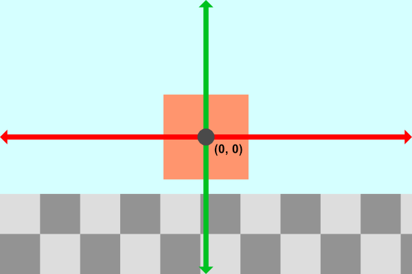
Our camera is sitting at a position defined by the variable, ro, which is the ray origin. Currently, it’s set equal to vec3(0, 0, 3). To pan the camera along the x-direction, we simply adjust the x-component of ro.
1vec3 ro = vec3(1, 0, 3);Our camera has now shifted to the right, which creates the effect of moving the cube to the left.
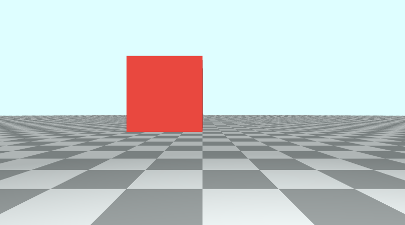
Likewise, we can adjust the y-component of ro to move the camera up or down.
1vec3 ro = vec3(0, 1, 3);Moving the camera up has the effect of moving the cube and floor down.
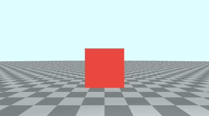
You can pan the camera along a circular path by using cos and sin functions along the x-axis and y-axis, respectively.
1vec3 ro = vec3(cos(iTime), sin(iTime) + 0.1, 3);
Obviously, it starts looking strange as you dip into the floor a bit, so I added 0.1 to the y-component to prevent flashing effects that may occur.
Tilting/Rotating the Camera
Suppose we want to keep the camera position, ro, the same, but we want to tilt the camera up, down, left, or right. Maybe we want to even turn the camera all the way around such that the camera turns around at a 180 degree angle. This involves applying a transformation matrix to the ray direction, rd.
Let’s set the ray origin back to normal:
1vec3 ro = vec3(0, 0, 3);The cube should look centered on the canvas now. Currently, our scene from a side view is similar to the following illustration:
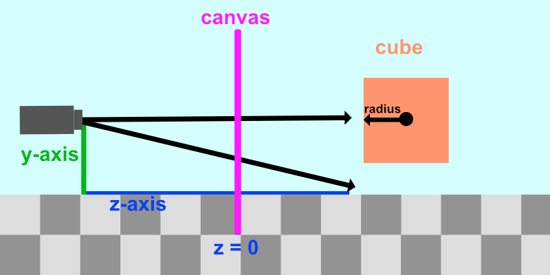
We want to keep the camera position the same but be able to tilt it in any direction. Suppose we wanted to tilt the camera upwards. Our scene would be similar to the following illustration:
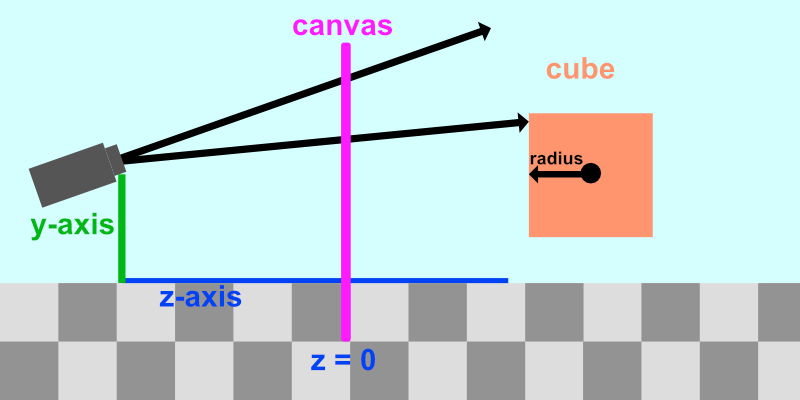
Notice how the rays being shot out of the camera have tilted upwards too. To tilt the camera means tilting all of the rays being fired out of the camera.
Tilting the camera is similar to the aircraft principal axes.
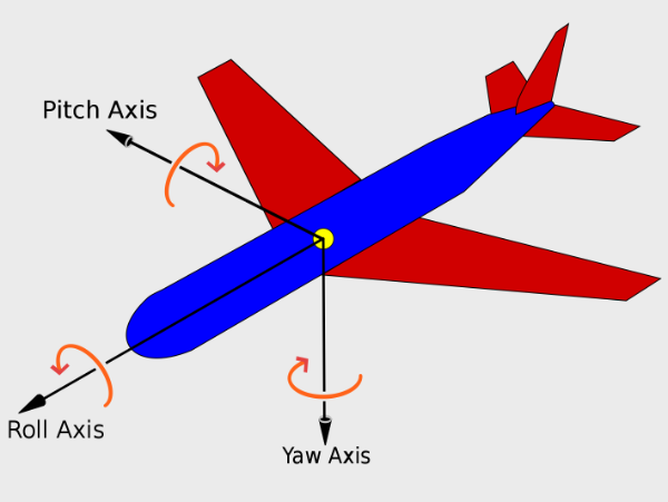
Aircraft principal axes by Wikipedia
The camera can not only pan along the x-axis, y-axis, or z-axis, but it can also tilt (or rotate) along three rotational axes: pitch, yaw, and roll. This means the camera has six degrees of freedom: three positional axes and three rotational axes.
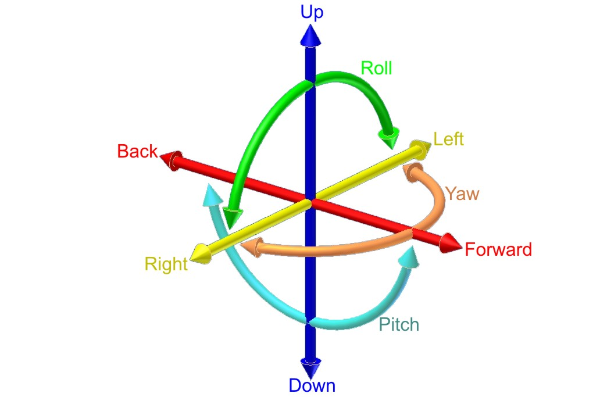
Six degrees of freedom (DOF) by Simple English Wikipedia
Luckily for us, we can use the same rotation matrices we used in the last tutorial to apply pitch, yaw, and roll.
“Pitch” is applied using the rotateX function, “yaw” is applied using the rotateY function, and “roll” is applied using the rotateZ function.
If we want to tilt the camera up/down, or apply “pitch,” then we need to apply the rotateX function to the ray direction, rd.
1vec3 rd = normalize(vec3(uv, -1));
2rd *= rotateX(0.3);
We simply multiply the ray direction by one or more rotation matrices to tilt the camera. That will tilt the direction of every ray fired from the camera, changing the view we see in the Shadertoy canvas.
Let’s animate the tilt such that the “pitch” angle oscillates between -0.5 and 0.5.
1vec3 rd = normalize(vec3(uv, -1));
2rd *= rotateX(sin(iTime) * 0.5);
To tilt the camera left/right, or apply “yaw”, we need to apply the rotateY function.
1vec3 rd = normalize(vec3(uv, -1));
2rd *= rotateY(sin(iTime) * 0.5);
To tilt the camera from side to side, or apply “roll”, we need to apply the rotateZ function. Do a barrel roll! 🐰
1vec3 rd = normalize(vec3(uv, -1));
2rd *= rotateZ(sin(iTime) * 0.5);
Rotating the Camera a Full 360
We can also apply yaw between negative pi and positive pi to spin the scene around a complete 360 degree angle.
1const float PI = 3.14159265359;
2vec3 rd = normalize(vec3(uv, -1));
3rd *= rotateY(sin(iTime * 0.5) * PI); // 0.5 is used to slow the animation down
When you look behind the camera, you’ll likely find a glowy spot on the ground. This glowy spot is the position of the light, currently set up at vec3(2, 2, 7). Since the positive z-axis is setup to be behind the camera typically, you end up seeing the light when you turn the camera around.
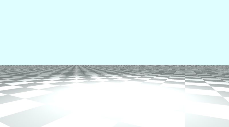
You make think the glowy spot is an April Fools’ joke, but it’s actually a result of the diffuse reflection calculation from Part 6.
1float dif = clamp(dot(normal, lightDirection), 0.3, 1.);
2col = dif * co.col + backgroundColor * .2;
Since we’re coloring the floor based on the diffuse reflection and the surface normal, the floor appears brightest where the light position is located. If you want to remove this sunspot, you’ll have to remove the floor from the lighting calculations.
Typically, this shouldn’t be an issue since the light is behind the camera. If you want to have scenes with a floor where the camera turns around, then you’ll probably want to remove the glowy spot.
Once approach to removing this “sun spot” or “sun glare” as I like to call it is to assign an ID to each object in the scene. Then, you can remove the floor from the lighting calculation by checking if the floor is the closest object in the scene after performing ray marching.
  1// Rotation matrix around the X axis.
  2mat3 rotateX(float theta) {
  3    float c = cos(theta);
  4    float s = sin(theta);
  5    return mat3(
  6        vec3(1, 0, 0),
  7        vec3(0, c, -s),
  8        vec3(0, s, c)
  9    );
 10}
 11
 12// Rotation matrix around the Y axis.
 13mat3 rotateY(float theta) {
 14    float c = cos(theta);
 15    float s = sin(theta);
 16    return mat3(
 17        vec3(c, 0, s),
 18        vec3(0, 1, 0),
 19        vec3(-s, 0, c)
 20    );
 21}
 22
 23// Rotation matrix around the Z axis.
 24mat3 rotateZ(float theta) {
 25    float c = cos(theta);
 26    float s = sin(theta);
 27    return mat3(
 28        vec3(c, -s, 0),
 29        vec3(s, c, 0),
 30        vec3(0, 0, 1)
 31    );
 32}
 33
 34// Identity matrix.
 35mat3 identity() {
 36    return mat3(
 37        vec3(1, 0, 0),
 38        vec3(0, 1, 0),
 39        vec3(0, 0, 1)
 40    );
 41}
 42
 43const int MAX_MARCHING_STEPS = 255;
 44const float MIN_DIST = 0.0;
 45const float MAX_DIST = 100.0;
 46const float PRECISION = 0.001;
 47
 48struct Surface {
 49    float sd; // signed distance value
 50    vec3 col; // color
 51    int id; // identifier for each surface/object
 52};
 53
 54/*
 55Surface IDs:
 561. Floor
 572. Box
 58*/
 59
 60Surface sdBox( vec3 p, vec3 b, vec3 offset, vec3 col, mat3 transform)
 61{
 62  p = (p - offset) * transform;
 63  vec3 q = abs(p) - b;
 64  float d = length(max(q,0.0)) + min(max(q.x,max(q.y,q.z)),0.0);
 65  return Surface(d, col, 2);
 66}
 67
 68Surface sdFloor(vec3 p, vec3 col) {
 69  float d = p.y + 1.;
 70  return Surface(d, col, 1);
 71}
 72
 73Surface minWithColor(Surface obj1, Surface obj2) {
 74  if (obj2.sd < obj1.sd) return obj2;
 75  return obj1;
 76}
 77
 78Surface sdScene(vec3 p) {
 79  vec3 floorColor = vec3(.5 + 0.3*mod(floor(p.x) + floor(p.z), 2.0));
 80  Surface co = sdFloor(p, floorColor);
 81  co = minWithColor(co, sdBox(p, vec3(1), vec3(0, 0.5, -4), vec3(1, 0, 0), identity()));
 82  return co;
 83}
 84
 85Surface rayMarch(vec3 ro, vec3 rd, float start, float end) {
 86  float depth = start;
 87  Surface co; // closest object
 88
 89  for (int i = 0; i < MAX_MARCHING_STEPS; i++) {
 90    vec3 p = ro + depth * rd;
 91    co = sdScene(p);
 92    depth += co.sd;
 93    if (co.sd < PRECISION || depth > end) break;
 94  }
 95
 96  co.sd = depth;
 97
 98  return co;
 99}
100
101vec3 calcNormal(in vec3 p) {
102    vec2 e = vec2(1.0, -1.0) * 0.0005; // epsilon
103    return normalize(
104      e.xyy * sdScene(p + e.xyy).sd +
105      e.yyx * sdScene(p + e.yyx).sd +
106      e.yxy * sdScene(p + e.yxy).sd +
107      e.xxx * sdScene(p + e.xxx).sd);
108}
109
110void mainImage( out vec4 fragColor, in vec2 fragCoord )
111{
112  vec2 uv = (fragCoord-.5*iResolution.xy)/iResolution.y;
113  vec3 backgroundColor = vec3(0.835, 1, 1);
114
115  vec3 col = vec3(0);
116  vec3 ro = vec3(0, 0, 3); // ray origin that represents camera position
117
118  const float PI = 3.14159265359;
119  vec3 rd = normalize(vec3(uv, -1));
120  rd *= rotateY(sin(iTime * 0.5) * PI); // 0.5 is used to slow the animation down
121
122  Surface co = rayMarch(ro, rd, MIN_DIST, MAX_DIST); // closest object
123
124  if (co.sd > MAX_DIST) {
125    col = backgroundColor; // ray didn't hit anything
126  } else {
127    vec3 p = ro + rd * co.sd; // point on cube or floor we discovered from ray marching
128    vec3 normal = calcNormal(p);
129
130    // check material ID
131    if( co.id == 1 ) // floor
132    {
133        col = co.col;
134    } else {
135      // lighting
136      vec3 lightPosition = vec3(2, 2, 7);
137      vec3 lightDirection = normalize(lightPosition - p);
138
139      // color
140      float dif = clamp(dot(normal, lightDirection), 0.3, 1.); // diffuse reflection
141      col = dif * co.col + backgroundColor * .2; // Add a bit of background color to the diffuse color
142    }
143  }
144
145  // Output to screen
146  fragColor = vec4(col, 1.0);
147}
With this approach, the floor lighting will look a bit different, but the sun spot will be gone!
By assigning IDs to each surface, material, or object, we can keep track of which object was hit by a ray after ray marching is performed. This can be useful for applying lighting or coloring calculations that are unique to one or more objects.
Understanding iMouse
Shadertoy provides a set of global variables that you can use in your shader code to make it more interactive. If you open a new shader and click on the arrow next to “Shader inputs,” then you’ll see a list of global variables.
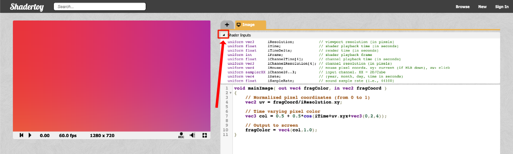
Below is a list of global variables you can use in Shadertoy shaders.
Shader Inputs
uniform vec3      iResolution;           // viewport resolution (in pixels)
uniform float     iTime;                 // shader playback time (in seconds)
uniform float     iTimeDelta;            // render time (in seconds)
uniform int       iFrame;                // shader playback frame
uniform float     iChannelTime[4];       // channel playback time (in seconds)
uniform vec3      iChannelResolution[4]; // channel resolution (in pixels)
uniform vec4      iMouse;                // mouse pixel coords. xy: current (if MLB down), zw: click
uniform samplerXX iChannel0..3;          // input channel. XX = 2D/Cube
uniform vec4      iDate;                 // (year, month, day, time in seconds)
uniform float     iSampleRate;           // sound sample rate (i.e., 44100)
Among them, you’ll see a variable called iMouse that can be used to get the position of your mouse as you click somewhere on the canvas. This variable is of type vec4 and therefore contains four pieces of information about a left mouse click.
vec4 mouse = iMouse;

mouse.xy = mouse position during last button down
abs(mouse.zw) = mouse position during last button click
sign(mouze.z) = button is down (positive if down)
sign(mouze.w) = button is clicked (positive if clicked)
A mouse click is what happens immediately after you press the mouse. A mouse down event is what happens after you continue holding it down.
This tutorial by Inigo Quilez, one of the co-creators of Shadertoy, shows you how to use each piece of data stored in iMouse. When you click anywhere in the scene, a white circle appears when you perform a mouse click. If you continue holding the mouse down and move the mouse around, a yellow line will appear between two circles. Once you release the mouse, the yellow line will disappear.
What we really care about for the purpose of this tutorial are the mouse coordinates. I made a small demo to show how you can move a circle around in the canvas using your mouse. Let’s look at the code:
 1float sdfCircle(vec2 uv, float r, vec2 offset) {
 2  float x = uv.x - offset.x;
 3  float y = uv.y - offset.y;
 4
 5  float d = length(vec2(x, y)) - r;
 6
 7  return step(0., -d);
 8}
 9
10vec3 drawScene(vec2 uv, vec2 mp) {
11  vec3 col = vec3(0);
12  float blueCircle = sdfCircle(uv, 0.1, mp);
13  col = mix(col, vec3(0, 1, 1), blueCircle);
14
15  return col;
16}
17
18void mainImage( out vec4 fragColor, in vec2 fragCoord )
19{
20  vec2 uv = fragCoord/iResolution.xy - 0.5; // <-0.5,0.5>
21  uv.x *= iResolution.x/iResolution.y; // fix aspect ratio
22
23  // mp = mouse position of the last click
24  vec2 mp = iMouse.xy/iResolution.xy - 0.5; // <-0.5,0.5>
25  mp.x *= iResolution.x/iResolution.y; // fix aspect ratio
26
27  vec3 col = drawScene(uv, mp);
28
29  // Output to screen
30  fragColor = vec4(col,1.0);
31}
Notice how getting the mouse position is very similar to the UV coordinates. We can normalize the coordinates through the following statement:
1vec2 mp = iMouse.xy/iResolution.xy // range is between 0 and 1This will normalize the mouse coordinates to be between zero and one. By subtracting 0.5, we can normalize the mouse coordinates to be between -0.5 and 0.5.
1vec2 mp = iMouse.xy/iResolution.xy - 0.5 // range is between -0.5 and 0.5Panning the Camera with the Mouse
Now that we understand how to use the iMouse global variable, let’s apply it to our camera. We can use the mouse to control panning by changing the value of the ray origin, ro.
1vec2 mouse = iMouse.xy / iResolution.xy - 0.5; // <-0.5,0.5>
2vec3 ro = vec3(mouse.x, mouse.y, 3); // ray origin will move as you click on the canvas and drag the mouse
If you click on the canvas and drag your mouse, you’ll be able to pan the camera between -0.5 and 0.5 on both the x-axis and y-axis. The center of the canvas will be the point, (0, 0), which should move the cube back in the center of the canvas.
If you want to pan more, you can always multiply the mouse position values by a multiplier.
1vec2 mouse = iMouse.xy / iResolution.xy - 0.5; // <-0.5,0.5>
2vec3 ro = vec3(2. * mouse.x, 2. * mouse.y, 3);
Tilting/Rotating the Camera with the Mouse
We can tilt/rotate the camera with the mouse by changing the value of theta, the angle we supply to our rotation matrices such as rotateX, rotateY, and rotateZ. Make sure that you’re no longer using the mouse to control the ray origin, ro. Otherwise, you may end up with a very strange camera.
Let’s apply “yaw” to the ray direction to tilt the camera left to right.
1vec2 mouse = iMouse.xy / iResolution.xy - 0.5; // <-0.5,0.5>
2vec3 rd = normalize(vec3(uv, -1)); // ray direction
3rd *= rotateY(mouse.x); // apply yaw
Since mouse.x is currently constrained between -0.5 and 0.5, it might make more sense to remap this range to something like negative pi (-π) to positive pi (+π). To remap a range to a new range, we can make use of the mix function. It’s already built to handle linear interpolation, so it’s perfect for remapping values from one range to another.
Let’s remap the range, <-0.5, 0.5>, to <-π, π>.
1vec2 mouse = iMouse.xy / iResolution.xy - 0.5; // <-0.5,0.5>
2vec3 rd = normalize(vec3(uv, -1)); // ray direction
3rd *= rotateY(mix(-PI, PI, mouse.x)); // apply yaw with a 360 degree range
Now, we can make a complete 360 rotation using our mouse!
You may be wondering how we can use the mouse.y value. We can use this value to tilt the camera up and down as the “pitch” angle. That means we need to leverage the rotateX function.
1vec2 mouse = iMouse.xy / iResolution.xy - 0.5; // <-0.5,0.5>
2vec3 rd = normalize(vec3(uv, -1)); // ray direction
3rd *= rotateX(mouse.y); // apply pitch
This will let us tilt the camera up and down between the values of -0.5 and 0.5.
If you want to use the mouse to change the “yaw” angle with mouse.x and “pitch” with mouse.y simultaneously, then we need to multiply the rotation matrices together.
1vec2 mouse = iMouse.xy / iResolution.xy - 0.5; // <-0.5,0.5>
2vec3 rd = normalize(vec3(uv, -1));
3rd *= rotateY(mouse.x) * rotateX(mouse.y); // apply yaw and pitch
Now, you can freely tilt the camera with your mouse to look around the scene! This can be handy for troubleshooting complex 3D scenes built with Shadertoy. In software such as Unity or Blender, you already have a powerful camera you can use to look around 3D scenes.
You can find the finished code below:
  1// Rotation matrix around the X axis.
  2mat3 rotateX(float theta) {
  3    float c = cos(theta);
  4    float s = sin(theta);
  5    return mat3(
  6        vec3(1, 0, 0),
  7        vec3(0, c, -s),
  8        vec3(0, s, c)
  9    );
 10}
 11
 12// Rotation matrix around the Y axis.
 13mat3 rotateY(float theta) {
 14    float c = cos(theta);
 15    float s = sin(theta);
 16    return mat3(
 17        vec3(c, 0, s),
 18        vec3(0, 1, 0),
 19        vec3(-s, 0, c)
 20    );
 21}
 22
 23// Rotation matrix around the Z axis.
 24mat3 rotateZ(float theta) {
 25    float c = cos(theta);
 26    float s = sin(theta);
 27    return mat3(
 28        vec3(c, -s, 0),
 29        vec3(s, c, 0),
 30        vec3(0, 0, 1)
 31    );
 32}
 33
 34// Identity matrix.
 35mat3 identity() {
 36    return mat3(
 37        vec3(1, 0, 0),
 38        vec3(0, 1, 0),
 39        vec3(0, 0, 1)
 40    );
 41}
 42
 43const int MAX_MARCHING_STEPS = 255;
 44const float MIN_DIST = 0.0;
 45const float MAX_DIST = 100.0;
 46const float PRECISION = 0.001;
 47
 48struct Surface {
 49    float sd; // signed distance value
 50    vec3 col; // color
 51    int id; // identifier for each surface/object
 52};
 53
 54/*
 55Surface IDs:
 561. Floor
 572. Box
 58*/
 59
 60Surface sdBox( vec3 p, vec3 b, vec3 offset, vec3 col, mat3 transform)
 61{
 62  p = (p - offset) * transform;
 63  vec3 q = abs(p) - b;
 64  float d = length(max(q,0.0)) + min(max(q.x,max(q.y,q.z)),0.0);
 65  return Surface(d, col, 2);
 66}
 67
 68Surface sdFloor(vec3 p, vec3 col) {
 69  float d = p.y + 1.;
 70  return Surface(d, col, 1);
 71}
 72
 73Surface minWithColor(Surface obj1, Surface obj2) {
 74  if (obj2.sd < obj1.sd) return obj2;
 75  return obj1;
 76}
 77
 78Surface sdScene(vec3 p) {
 79  vec3 floorColor = vec3(.5 + 0.3*mod(floor(p.x) + floor(p.z), 2.0));
 80  Surface co = sdFloor(p, floorColor);
 81  co = minWithColor(co, sdBox(p, vec3(1), vec3(0, 0.5, -4), vec3(1, 0, 0), identity()));
 82  return co;
 83}
 84
 85Surface rayMarch(vec3 ro, vec3 rd, float start, float end) {
 86  float depth = start;
 87  Surface co; // closest object
 88
 89  for (int i = 0; i < MAX_MARCHING_STEPS; i++) {
 90    vec3 p = ro + depth * rd;
 91    co = sdScene(p);
 92    depth += co.sd;
 93    if (co.sd < PRECISION || depth > end) break;
 94  }
 95
 96  co.sd = depth;
 97
 98  return co;
 99}
100
101vec3 calcNormal(in vec3 p) {
102    vec2 e = vec2(1.0, -1.0) * 0.0005; // epsilon
103    return normalize(
104      e.xyy * sdScene(p + e.xyy).sd +
105      e.yyx * sdScene(p + e.yyx).sd +
106      e.yxy * sdScene(p + e.yxy).sd +
107      e.xxx * sdScene(p + e.xxx).sd);
108}
109
110void mainImage( out vec4 fragColor, in vec2 fragCoord )
111{
112  vec2 uv = (fragCoord-.5*iResolution.xy)/iResolution.y;
113  vec3 backgroundColor = vec3(0.835, 1, 1);
114
115  vec3 col = vec3(0);
116  vec3 ro = vec3(0, 0, 3); // ray origin that represents camera position
117
118  vec2 mouse = iMouse.xy / iResolution.xy - 0.5; // <-0.5,0.5>
119  vec3 rd = normalize(vec3(uv, -1)); // ray direction
120  rd *= rotateY(mouse.x) * rotateX(mouse.y); // apply yaw and pitch
121
122
123  Surface co = rayMarch(ro, rd, MIN_DIST, MAX_DIST); // closest object
124
125  if (co.sd > MAX_DIST) {
126    col = backgroundColor; // ray didn't hit anything
127  } else {
128    vec3 p = ro + rd * co.sd; // point on cube or floor we discovered from ray marching
129    vec3 normal = calcNormal(p);
130
131    // check material ID
132    if( co.id == 1 ) // floor
133    {
134        col = co.col;
135    } else {
136      // lighting
137      vec3 lightPosition = vec3(2, 2, 7);
138      vec3 lightDirection = normalize(lightPosition - p);
139
140      // color
141      float dif = clamp(dot(normal, lightDirection), 0.3, 1.); // diffuse reflection
142      col = dif * co.col + backgroundColor * .2; // Add a bit of background color to the diffuse color
143    }
144  }
145
146  // Output to screen
147  fragColor = vec4(col, 1.0);
148}
Conclusion
In this tutorial, we learned how to move the camera in six degrees of freedom. We learned how to pan the camera around along the x-axis, y-axis, and z-axis. We also learned how to use rotation matrices to apply yaw, pitch, and roll, so we can control the camera’s tilt. Using the knowledge you’ve learned today, you can debug 3D scenes in Shadertoy and make interesting animations.
Resources
- Aircraft Principal Axes
- Pitch, Yaw, and Roll
- Rotation Matrices
- Shadertoy: Input - Mouse
- Shadertoy: 2D Movement with Mouse
- Shadertoy: Panning and Tilting the Camera Example
Tutorial Part 10 - Camera Model with a Lookat Point
转自:https://inspirnathan.com/posts/56-shadertoy-tutorial-part-10
Greetings, friends! Welcome to Part 10 of my Shadertoy tutorial series. In this tutorial, we’ll learn how to make a more flexible camera model that uses a lookat point. This will make it easier to change what objects the camera is looking at.
Initial Setup
Let’s create a new shader and add the following boilerplate code we’ll use for this tutorial. Notice how the constants are now defined at the top of the code.
  1// Constants
  2const int MAX_MARCHING_STEPS = 255;
  3const float MIN_DIST = 0.0;
  4const float MAX_DIST = 100.0;
  5const float PRECISION = 0.001;
  6const float EPSILON = 0.0005;
  7const float PI = 3.14159265359;
  8
  9// Rotation matrix around the X axis.
 10mat3 rotateX(float theta) {
 11    float c = cos(theta);
 12    float s = sin(theta);
 13    return mat3(
 14        vec3(1, 0, 0),
 15        vec3(0, c, -s),
 16        vec3(0, s, c)
 17    );
 18}
 19
 20// Rotation matrix around the Y axis.
 21mat3 rotateY(float theta) {
 22    float c = cos(theta);
 23    float s = sin(theta);
 24    return mat3(
 25        vec3(c, 0, s),
 26        vec3(0, 1, 0),
 27        vec3(-s, 0, c)
 28    );
 29}
 30
 31// Rotation matrix around the Z axis.
 32mat3 rotateZ(float theta) {
 33    float c = cos(theta);
 34    float s = sin(theta);
 35    return mat3(
 36        vec3(c, -s, 0),
 37        vec3(s, c, 0),
 38        vec3(0, 0, 1)
 39    );
 40}
 41
 42// Identity matrix.
 43mat3 identity() {
 44    return mat3(
 45        vec3(1, 0, 0),
 46        vec3(0, 1, 0),
 47        vec3(0, 0, 1)
 48    );
 49}
 50
 51struct Surface {
 52    float sd; // signed distance value
 53    vec3 col; // color
 54};
 55
 56Surface sdBox( vec3 p, vec3 b, vec3 offset, vec3 col, mat3 transform)
 57{
 58  p = (p - offset) * transform; // apply transformation matrix
 59  vec3 q = abs(p) - b;
 60  float d = length(max(q,0.0)) + min(max(q.x,max(q.y,q.z)),0.0);
 61  return Surface(d, col);
 62}
 63
 64Surface sdFloor(vec3 p, vec3 col) {
 65  float d = p.y + 1.;
 66  return Surface(d, col);
 67}
 68
 69Surface minWithColor(Surface obj1, Surface obj2) {
 70  if (obj2.sd < obj1.sd) return obj2;
 71  return obj1;
 72}
 73
 74Surface sdScene(vec3 p) {
 75  vec3 floorColor = vec3(1. + 0.7*mod(floor(p.x) + floor(p.z), 2.0));
 76  Surface co = sdFloor(p, floorColor);
 77  co = minWithColor(co, sdBox(p, vec3(1), vec3(-4, 0.5, -4), vec3(1, 0, 0), identity())); // left cube
 78  co = minWithColor(co, sdBox(p, vec3(1), vec3(0, 0.5, -4), vec3(0, 0.65, 0.2), identity())); // center cube
 79  co = minWithColor(co, sdBox(p, vec3(1), vec3(4, 0.5, -4), vec3(0, 0.55, 2), identity())); // right cube
 80  return co;
 81}
 82
 83Surface rayMarch(vec3 ro, vec3 rd, float start, float end) {
 84  float depth = start;
 85  Surface co; // closest object
 86
 87  for (int i = 0; i < MAX_MARCHING_STEPS; i++) {
 88    vec3 p = ro + depth * rd;
 89    co = sdScene(p);
 90    depth += co.sd;
 91    if (co.sd < PRECISION || depth > end) break;
 92  }
 93
 94  co.sd = depth;
 95
 96  return co;
 97}
 98
 99vec3 calcNormal(in vec3 p) {
100    vec2 e = vec2(1, -1) * EPSILON;
101    return normalize(
102      e.xyy * sdScene(p + e.xyy).sd +
103      e.yyx * sdScene(p + e.yyx).sd +
104      e.yxy * sdScene(p + e.yxy).sd +
105      e.xxx * sdScene(p + e.xxx).sd);
106}
107
108void mainImage( out vec4 fragColor, in vec2 fragCoord )
109{
110  vec2 uv = (fragCoord-.5*iResolution.xy)/iResolution.y;
111  vec3 backgroundColor = vec3(0.835, 1, 1);
112
113  vec3 col = vec3(0);
114  vec3 ro = vec3(0, 0, 3); // ray origin that represents camera position
115  vec3 rd = normalize(vec3(uv, -1)); // ray direction
116
117  Surface co = rayMarch(ro, rd, MIN_DIST, MAX_DIST); // closest object
118
119  if (co.sd > MAX_DIST) {
120    col = backgroundColor; // ray didn't hit anything
121  } else {
122    vec3 p = ro + rd * co.sd; // point on cube or floor we discovered from ray marching
123    vec3 normal = calcNormal(p);
124    vec3 lightPosition = vec3(2, 2, 7);
125    vec3 lightDirection = normalize(lightPosition - p);
126
127    float dif = clamp(dot(normal, lightDirection), 0.3, 1.); // diffuse reflection
128
129    col = dif * co.col + backgroundColor * .2; // Add a bit of background color to the diffuse color
130  }
131
132  // Output to screen
133  fragColor = vec4(col, 1.0);
134}
This code will produce a scene with three cubes, each with different colors: red, green, and blue.

The LookAt Point
Currently, when we want to move the camera, we have to adjust the values of the ray origin. To tilt the camera, we need to multiply the ray direction by a rotation matrix.
An alternative approach is to create a camera function that accepts the camera position (or ray origin), and a lookat point. Then, this function will return a 3x3 transformation matrix we can multiply the ray direction by.
1mat3 camera(vec3 cameraPos, vec3 lookAtPoint) {
2	vec3 cd = normalize(lookAtPoint - cameraPos); // camera direction
3	vec3 cr = normalize(cross(vec3(0, 1, 0), cd)); // camera right
4	vec3 cu = normalize(cross(cd, cr)); // camera up
5
6	return mat3(-cr, cu, -cd);
7}
To understand how we came up with this matrix, let’s look at the image below. It was created on the website, Learn OpenGL, an amazing resource for learning the OpenGL graphics API.
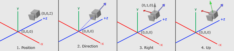
Camera/view space by Learn OpenGL
The image above conveys a lot about how the 3x3 matrix was created. We need to figure out where the camera is looking at and how it’s tilted by analyzing three important camera vectors: the “camera direction” vector, the “camera right” vector, and the “camera up” vector.
In step 1, we start with the camera position, which is equal to the ray origin, ro, in our code.
In step 2, we create a camera direction vector that is relative to a “lookat” point. In the image, the lookat point is located at the origin in 3D space, but we can shift this point anywhere we want. Notice how the camera direction is pointing away from the camera. This means it’s using the right-hand rule we learned about in Part 6.
1vec3 cd = normalize(lookAtPoint - cameraPos); // camera directionIn step 3, there is a gray vector pointing straight up from the camera. The direction vector, (0, 1, 0), represents a unit vector for the y-axis. we create the “camera right” vector by taking the cross product between the unit vector of the y-axis and the camera direction. This creates the red vector pointing to the right of the camera.
1normalize(cross(vec3(0, 1, 0), cd)); // camera rightIn step 4, we then find the “camera up” vector by taking the cross product between the camera direction vector and the “camera right” vector. This “camera up” vector is depicted in the image by a green vector sticking out of the camera.
1vec3 cu = normalize(cross(cd, cr)); // camera upFinally, we create a transformation matrix by combining these vectors together:
1mat3 camera(vec3 cameraPos, vec3 lookAtPoint) {
2	vec3 cd = normalize(lookAtPoint - cameraPos); // camera direction
3	vec3 cr = normalize(cross(vec3(0, 1, 0), cd)); // camera right
4	vec3 cu = normalize(cross(cd, cr)); // camera up
5
6	return mat3(-cr, cu, -cd); // negative signs can be turned positive (or vice versa) to flip coordinate space conventions
7}
Let’s look at the return statement for the camera function:
1return mat3(-cr, cu, -cd);Where did the negative signs come from? It’s up to us to define a convention for how we want to label which direction is positive or negative for each axis in 3D space. This is the convention I will use in this tutorial. We’ll see what happens when we flip the signs soon.
Applying the Camera Matrix
Now that we have created a camera function, let’s use it in our mainImage function. We’ll create a lookat point and pass it to the camera function. Then, we’ll multiply the matrix it returns by the ray direction, similar to what we did in Part 9.
1vec3 lp = vec3(0, 0, 0); // lookat point (aka camera target)
2vec3 ro = vec3(0, 0, 3); // ray origin that represents camera position
3vec3 rd = camera(ro, lp) * normalize(vec3(uv, -1)); // ray direction
When you run your code, the scene should look almost the same. However, the camera is now targeting the origin in 3D space. Since the cubes are 0.5 units off the ground, the camera is slightly tilted from the center. We can point the camera directly at the center of the green cube by changing the lookat point to match the position of the green cube.
1vec3 lp = vec3(0, 0.5, -4);Suppose we want to look at the red cube now. It currently has the position, (-4, 0.5, -4) in 3D space. Let’s change the lookat point to match that position.
1vec3 lp = vec3(-4, 0.5, -4);You should see the camera now pointing at the red cube, and it should be in the center of the canvas.
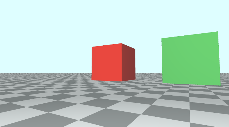
Let’s now look at the blue cube. It has the position, (4, 0.5, -4) in 3D space, so we’ll change the lookat point to equal that value.
1vec3 lp = vec3(4, 0.5, -4);You should see the camera now pointing at the blue cube, and it should be in the center of the canvas.
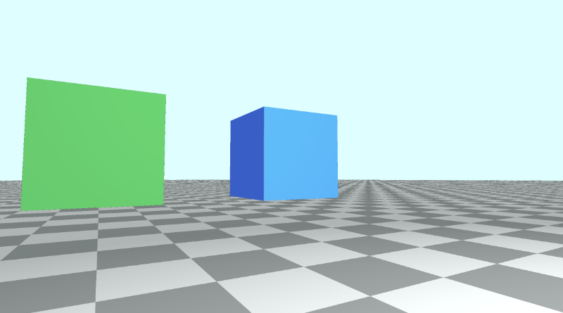
You can find the finished code below:
  1// Constants
  2const int MAX_MARCHING_STEPS = 255;
  3const float MIN_DIST = 0.0;
  4const float MAX_DIST = 100.0;
  5const float PRECISION = 0.001;
  6const float EPSILON = 0.0005;
  7const float PI = 3.14159265359;
  8
  9// Rotation matrix around the X axis.
 10mat3 rotateX(float theta) {
 11    float c = cos(theta);
 12    float s = sin(theta);
 13    return mat3(
 14        vec3(1, 0, 0),
 15        vec3(0, c, -s),
 16        vec3(0, s, c)
 17    );
 18}
 19
 20// Rotation matrix around the Y axis.
 21mat3 rotateY(float theta) {
 22    float c = cos(theta);
 23    float s = sin(theta);
 24    return mat3(
 25        vec3(c, 0, s),
 26        vec3(0, 1, 0),
 27        vec3(-s, 0, c)
 28    );
 29}
 30
 31// Rotation matrix around the Z axis.
 32mat3 rotateZ(float theta) {
 33    float c = cos(theta);
 34    float s = sin(theta);
 35    return mat3(
 36        vec3(c, -s, 0),
 37        vec3(s, c, 0),
 38        vec3(0, 0, 1)
 39    );
 40}
 41
 42// Identity matrix.
 43mat3 identity() {
 44    return mat3(
 45        vec3(1, 0, 0),
 46        vec3(0, 1, 0),
 47        vec3(0, 0, 1)
 48    );
 49}
 50
 51struct Surface {
 52    float sd; // signed distance value
 53    vec3 col; // color
 54};
 55
 56Surface sdBox( vec3 p, vec3 b, vec3 offset, vec3 col, mat3 transform)
 57{
 58  p = (p - offset) * transform; // apply transformation matrix
 59  vec3 q = abs(p) - b;
 60  float d = length(max(q,0.0)) + min(max(q.x,max(q.y,q.z)),0.0);
 61  return Surface(d, col);
 62}
 63
 64Surface sdFloor(vec3 p, vec3 col) {
 65  float d = p.y + 1.;
 66  return Surface(d, col);
 67}
 68
 69Surface minWithColor(Surface obj1, Surface obj2) {
 70  if (obj2.sd < obj1.sd) return obj2;
 71  return obj1;
 72}
 73
 74Surface sdScene(vec3 p) {
 75  vec3 floorColor = vec3(1. + 0.7*mod(floor(p.x) + floor(p.z), 2.0));
 76  Surface co = sdFloor(p, floorColor);
 77  co = minWithColor(co, sdBox(p, vec3(1), vec3(-4, 0.5, -4), vec3(1, 0, 0), identity())); // left cube
 78  co = minWithColor(co, sdBox(p, vec3(1), vec3(0, 0.5, -4), vec3(0, 0.65, 0.2), identity())); // center cube
 79  co = minWithColor(co, sdBox(p, vec3(1), vec3(4, 0.5, -4), vec3(0, 0.55, 2), identity())); // right cube
 80  return co;
 81}
 82
 83Surface rayMarch(vec3 ro, vec3 rd, float start, float end) {
 84  float depth = start;
 85  Surface co; // closest object
 86
 87  for (int i = 0; i < MAX_MARCHING_STEPS; i++) {
 88    vec3 p = ro + depth * rd;
 89    co = sdScene(p);
 90    depth += co.sd;
 91    if (co.sd < PRECISION || depth > end) break;
 92  }
 93
 94  co.sd = depth;
 95
 96  return co;
 97}
 98
 99vec3 calcNormal(in vec3 p) {
100    vec2 e = vec2(1, -1) * EPSILON;
101    return normalize(
102      e.xyy * sdScene(p + e.xyy).sd +
103      e.yyx * sdScene(p + e.yyx).sd +
104      e.yxy * sdScene(p + e.yxy).sd +
105      e.xxx * sdScene(p + e.xxx).sd);
106}
107
108mat3 camera(vec3 cameraPos, vec3 lookAtPoint) {
109	vec3 cd = normalize(lookAtPoint - cameraPos); // camera direction
110	vec3 cr = normalize(cross(vec3(0, 1, 0), cd)); // camera right
111	vec3 cu = normalize(cross(cd, cr)); // camera up
112
113	return mat3(-cr, cu, -cd);
114}
115
116void mainImage( out vec4 fragColor, in vec2 fragCoord )
117{
118  vec2 uv = (fragCoord-.5*iResolution.xy)/iResolution.y;
119  vec3 backgroundColor = vec3(0.835, 1, 1);
120
121  vec3 col = vec3(0);
122  vec3 lp = vec3(4, 0.5, -4); // lookat point (aka camera target)
123  vec3 ro = vec3(0, 0, 3); // ray origin that represents camera position
124  vec3 rd = camera(ro, lp) * normalize(vec3(uv, -1)); // ray direction
125
126  Surface co = rayMarch(ro, rd, MIN_DIST, MAX_DIST); // closest object
127
128  if (co.sd > MAX_DIST) {
129    col = backgroundColor; // ray didn't hit anything
130  } else {
131    vec3 p = ro + rd * co.sd; // point on cube or floor we discovered from ray marching
132    vec3 normal = calcNormal(p);
133    vec3 lightPosition = vec3(2, 2, 7);
134    vec3 lightDirection = normalize(lightPosition - p);
135
136    float dif = clamp(dot(normal, lightDirection), 0.3, 1.); // diffuse reflection
137
138    col = dif * co.col + backgroundColor * .2; // Add a bit of background color to the diffuse color
139  }
140
141  // Output to screen
142  fragColor = vec4(col, 1.0);
143}
Adjusting the Sign Convention
Earlier, we saw that the camera function returns a matrix consisting of the three camera vectors.
1mat3 camera(vec3 cameraPos, vec3 lookAtPoint) {
2	vec3 cd = normalize(lookAtPoint - cameraPos); // camera direction
3	vec3 cr = normalize(cross(vec3(0, 1, 0), cd)); // camera right
4	vec3 cu = normalize(cross(cd, cr)); // camera up
5
6	return mat3(-cr, cu, -cd);
7}
If we setup the lookat point to point the camera at the green cube, we have the following code:
1vec3 lp = vec3(0, 0.5, -4); // lookat point (aka camera target)
2vec3 ro = vec3(0, 0, 3); // ray origin that represents camera position
3vec3 rd = camera(ro, lp) * normalize(vec3(uv, -1)); // ray direction
This produces the scene from the beginning of this tutorial where the red cube is on the left of the green cube, and the blue cube is on the right of the green cube.
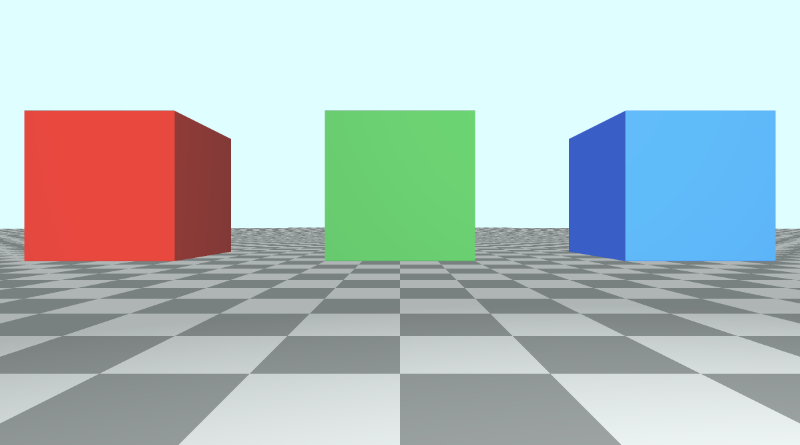
If we decide to use a positive cr value in the camera function, then let’s see what happens.
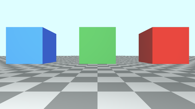
The red cube and blue cube seem to switch places, but pay attention to the floor tiles. They are switched too. The “camera right” vector is reversed which causes the whole scene to flip like looking at a mirror image of the original scene.
Using a positive cr impacts what the camera sees and also makes the position of our cubes seem confusing. Our x-axis is designed to be negative on the left of the center of the canvas and positive on the right of the center. Flipping cr means flipping that convention too.
If we flipped the value of the camera direction, cd to be positive instead of negative, it would turn the camera around because it would flip our z-axis convention.
Another way you can flip the z-axis convention is by using a positive value for the z-component of the ray direction.
1vec3 rd = normalize(vec3(uv, 1)); // positive one is being used instead of negative oneWhen you use this alternative camera model with a lookat point, it’s good to know the conventions you’ve set for what’s positive or negative across each axis.
You can play around with cr, cu, and cd to make some interesting effects. Make sure to change the ray direction, rd, back to using negative one.
The following code can create a slingshot effect across the z-axis to make it look like the camera zooms out and zooms in really quickly. Maybe this could be used to create a “warp drive” effect? 🤔
1mat3 camera(vec3 cameraPos, vec3 lookAtPoint) {
2	vec3 cd = normalize(lookAtPoint - cameraPos); // camera direction
3	vec3 cr = normalize(cross(vec3(0, 1, 0), cd)); // camera right
4	vec3 cu = normalize(cross(cd, cr)); // camera up
5
6	return mat3(-cr, cu, abs(cos(iTime)) * -cd);
7}
Go ahead and change the camera matrix back to normal before continuing to the next part of the tutorial.
1mat3 camera(vec3 cameraPos, vec3 lookAtPoint) {
2	vec3 cd = normalize(lookAtPoint - cameraPos); // camera direction
3	vec3 cr = normalize(cross(vec3(0, 1, 0), cd)); // camera right
4	vec3 cu = normalize(cross(cd, cr)); // camera up
5
6	return mat3(-cr, cu, -cd);
7}
Rotating the Camera Around a Target
Suppose we wanted to rotate our camera in a circular path around the scene while keeping our camera pointed at the green cube. We’ll keep the camera at a constant height (y-component) above the floor. Since all three cubes have a position with a y-component of 0.5, we will make sure the y-component of ro, the ray origin (camera position), equals 0.5 as well.
If we want to make the camera follow a circular path around the size of the cubes, then we should focus on changing the x-component and z-component of the ray origin, ro.
If we looked at the cubes from a top-down perspective, then we would see a view similar to the following illustration.
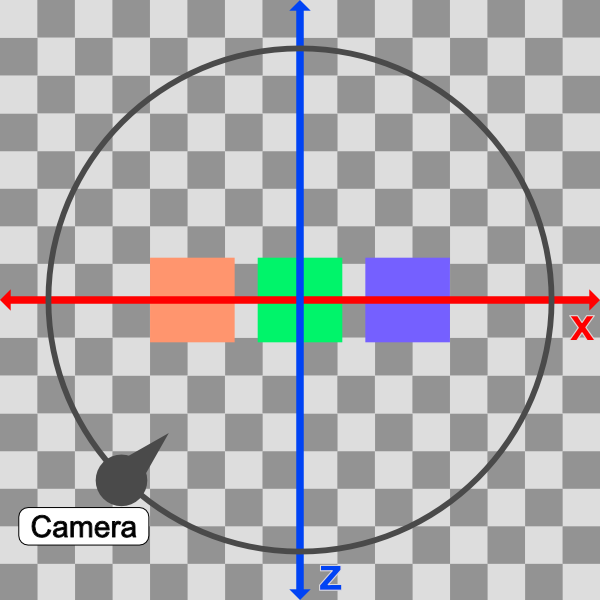
In the image above, the camera will follow a circular path (black). From a top-down perspective, the scene appears 2D with just an x-axis (red) and z-axis (blue).
The idea is to alter the x-component and z-component values of ro such that it follows a circular path. We can accomplish this by converting ro.x and ro.z into polar coordinates.
1vec3 ro = vec3(0, 0.5, 0);
2ro.x = cameraRadius * cos(theta);
3ro.z = cameraRadius * sin(theta);
The value of the camera radius will be increased until we can see all the cubes in our scene. We currently have three cubes at the following positions in 3D space (defined in the sdScene function):
1vec3(-4, 0.5, -4) // left cube
2vec3(0, 0.5, -4) // center cube
3vec3(4, 0.5, -4) // right cube
Therefore, it might be safe to make the radius something like 10 because the distance between the left cube and right cube is 4 - (-4) = 8 units.
In our code, we’ll convert the x-component and z-component of the ray origin to polar coordinates with a radius of ten. Then, we’ll also shift our circular path by an offset such that the lookat point is the center of the circle made by the circular path.
1vec3 lp = vec3(0, 0.5, -4); // lookat point (aka camera target)
2vec3 ro = vec3(0, 0.5, 0); // ray origin that represents camera position
3
4float cameraRadius = 10.;
5ro.x = cameraRadius * cos(iTime) + lp.x; // convert x-component to polar and add offset
6ro.z = cameraRadius * sin(iTime) + lp.z; // convert z-component to polar and add offset
7
8vec3 rd = camera(ro, lp) * normalize(vec3(uv, -1)); // ray direction
When you run the code, you should see the camera spinning around the scene because it’s following a circular path, but it’s still looking at the green cube using our lookat point.
From a top-down perspective, our camera is moving in a circle that is offset by the lookat point’s x-component and z-component, so we can make sure the lookat point stays in the center of our circle. This ensures that the distance from the green cube, the radius of the circle, stays equidistant from the green cube throughout the whole revolution.
You can use the graph I created on Desmos to experiment with the circular path. Imagine the green cube is located in the center of the circle.
Using a lookat point makes our camera more flexible. We can raise the camera higher along the y-axis and rotate around in a circle again, but get a bird’s-eye view of the cubes instead.
Let’s try adjusting the height of the camera (ray origin) and see what happens.
1vec3 ro = vec3(0, 5, 0);When we run the code, we should see the camera now circling around the three cubes, but it’s at a higher position. It’s like we’re a news reporter flying around in a helicopter.
If you change the lookat point, you should start rotating around that new point instead!
You can find the finished code below:
  1// Constants
  2const int MAX_MARCHING_STEPS = 255;
  3const float MIN_DIST = 0.0;
  4const float MAX_DIST = 100.0;
  5const float PRECISION = 0.001;
  6const float EPSILON = 0.0005;
  7const float PI = 3.14159265359;
  8
  9// Rotation matrix around the X axis.
 10mat3 rotateX(float theta) {
 11    float c = cos(theta);
 12    float s = sin(theta);
 13    return mat3(
 14        vec3(1, 0, 0),
 15        vec3(0, c, -s),
 16        vec3(0, s, c)
 17    );
 18}
 19
 20// Rotation matrix around the Y axis.
 21mat3 rotateY(float theta) {
 22    float c = cos(theta);
 23    float s = sin(theta);
 24    return mat3(
 25        vec3(c, 0, s),
 26        vec3(0, 1, 0),
 27        vec3(-s, 0, c)
 28    );
 29}
 30
 31// Rotation matrix around the Z axis.
 32mat3 rotateZ(float theta) {
 33    float c = cos(theta);
 34    float s = sin(theta);
 35    return mat3(
 36        vec3(c, -s, 0),
 37        vec3(s, c, 0),
 38        vec3(0, 0, 1)
 39    );
 40}
 41
 42// Identity matrix.
 43mat3 identity() {
 44    return mat3(
 45        vec3(1, 0, 0),
 46        vec3(0, 1, 0),
 47        vec3(0, 0, 1)
 48    );
 49}
 50
 51struct Surface {
 52    float sd; // signed distance value
 53    vec3 col; // color
 54};
 55
 56Surface sdBox( vec3 p, vec3 b, vec3 offset, vec3 col, mat3 transform)
 57{
 58  p = (p - offset) * transform; // apply transformation matrix
 59  vec3 q = abs(p) - b;
 60  float d = length(max(q,0.0)) + min(max(q.x,max(q.y,q.z)),0.0);
 61  return Surface(d, col);
 62}
 63
 64Surface sdFloor(vec3 p, vec3 col) {
 65  float d = p.y + 1.;
 66  return Surface(d, col);
 67}
 68
 69Surface minWithColor(Surface obj1, Surface obj2) {
 70  if (obj2.sd < obj1.sd) return obj2;
 71  return obj1;
 72}
 73
 74Surface sdScene(vec3 p) {
 75  vec3 floorColor = vec3(1. + 0.7*mod(floor(p.x) + floor(p.z), 2.0));
 76  Surface co = sdFloor(p, floorColor);
 77  co = minWithColor(co, sdBox(p, vec3(1), vec3(-4, 0.5, -4), vec3(1, 0, 0), identity())); // left cube
 78  co = minWithColor(co, sdBox(p, vec3(1), vec3(0, 0.5, -4), vec3(0, 0.65, 0.2), identity())); // center cube
 79  co = minWithColor(co, sdBox(p, vec3(1), vec3(4, 0.5, -4), vec3(0, 0.55, 2), identity())); // right cube
 80  return co;
 81}
 82
 83Surface rayMarch(vec3 ro, vec3 rd, float start, float end) {
 84  float depth = start;
 85  Surface co; // closest object
 86
 87  for (int i = 0; i < MAX_MARCHING_STEPS; i++) {
 88    vec3 p = ro + depth * rd;
 89    co = sdScene(p);
 90    depth += co.sd;
 91    if (co.sd < PRECISION || depth > end) break;
 92  }
 93
 94  co.sd = depth;
 95
 96  return co;
 97}
 98
 99vec3 calcNormal(in vec3 p) {
100    vec2 e = vec2(1, -1) * EPSILON;
101    return normalize(
102      e.xyy * sdScene(p + e.xyy).sd +
103      e.yyx * sdScene(p + e.yyx).sd +
104      e.yxy * sdScene(p + e.yxy).sd +
105      e.xxx * sdScene(p + e.xxx).sd);
106}
107
108mat3 camera(vec3 cameraPos, vec3 lookAtPoint) {
109	vec3 cd = normalize(lookAtPoint - cameraPos); // camera direction
110	vec3 cr = normalize(cross(vec3(0, 1, 0), cd)); // camera right
111	vec3 cu = normalize(cross(cd, cr)); // camera up
112
113	return mat3(-cr, cu, -cd);
114}
115
116void mainImage( out vec4 fragColor, in vec2 fragCoord )
117{
118  vec2 uv = (fragCoord-.5*iResolution.xy)/iResolution.y;
119  vec3 backgroundColor = vec3(0.835, 1, 1);
120
121  vec3 col = vec3(0);
122  vec3 lp = vec3(0, 0.5, -4); // lookat point (aka camera target)
123  vec3 ro = vec3(0, 5, 0); // ray origin that represents camera position
124
125  float cameraRadius = 10.;
126  ro.x = cameraRadius * cos(iTime) + lp.x; // convert to polar
127  ro.z = cameraRadius * sin(iTime) + lp.z;
128
129  vec3 rd = camera(ro, lp) * normalize(vec3(uv, -1)); // ray direction
130
131  Surface co = rayMarch(ro, rd, MIN_DIST, MAX_DIST); // closest object
132
133  if (co.sd > MAX_DIST) {
134    col = backgroundColor; // ray didn't hit anything
135  } else {
136    vec3 p = ro + rd * co.sd; // point on cube or floor we discovered from ray marching
137    vec3 normal = calcNormal(p);
138    vec3 lightPosition = vec3(2, 2, 7);
139    vec3 lightDirection = normalize(lightPosition - p);
140
141    float dif = clamp(dot(normal, lightDirection), 0.3, 1.); // diffuse reflection
142
143    col = dif * co.col + backgroundColor * .2; // Add a bit of background color to the diffuse color
144  }
145
146  // Output to screen
147  fragColor = vec4(col, 1.0);
148}
Rotating the Camera with the Mouse
You can also use the mouse to move the camera around the scene, but it requires some extra setup. As we learned in Part 9 of this tutorial series, the iMouse global variable provides the mouse position data.
We can create “mouse UV” coordinates using the following line:
1vec2 mouseUV = iMouse.xy/iResolution.xy; // Range: <0, 1>We’ll replace the following three lines, since we’re using our mouse to rotate around the scene instead of using time.
1float cameraRadius = 10.;
2ro.x = cameraRadius * cos(iTime) + lp.x; // convert to polar
3ro.z = cameraRadius * sin(iTime) + lp.z;
The following code will replace the above code:
1float cameraRadius = 2.;
2ro.yz = ro.yz * cameraRadius * rotate2d(mix(PI/2., 0., mouseUV.y));
3ro.xz = ro.xz * rotate2d(mix(-PI, PI, mouseUV.x)) + vec2(lp.x, lp.z); // remap mouseUV.x to <-pi, pi> range
Again, we’re using the mix function to remap the x-component of the mouse position. This time, we’re remapping values from the <0,1> range to the <-π, π> range. We also need to add the x-component and z-component of the lookat point.
Notice that we have a rotate2d function that doesn’t specify an axis. This function will provide a 2D rotation using a 2D matrix. Add the following function at the top of your code.
1mat2 rotate2d(float theta) {
2  float s = sin(theta), c = cos(theta);
3  return mat2(c, -s, s, c);
4}
Like before, you may need to play around with the cameraRadius until it looks decent. Your finished code should look like the following:
  1// Constants
  2const int MAX_MARCHING_STEPS = 255;
  3const float MIN_DIST = 0.0;
  4const float MAX_DIST = 100.0;
  5const float PRECISION = 0.001;
  6const float EPSILON = 0.0005;
  7const float PI = 3.14159265359;
  8
  9// Rotate around a circular path
 10mat2 rotate2d(float theta) {
 11  float s = sin(theta), c = cos(theta);
 12  return mat2(c, -s, s, c);
 13}
 14
 15// Rotation matrix around the X axis.
 16mat3 rotateX(float theta) {
 17    float c = cos(theta);
 18    float s = sin(theta);
 19    return mat3(
 20        vec3(1, 0, 0),
 21        vec3(0, c, -s),
 22        vec3(0, s, c)
 23    );
 24}
 25
 26// Rotation matrix around the Y axis.
 27mat3 rotateY(float theta) {
 28    float c = cos(theta);
 29    float s = sin(theta);
 30    return mat3(
 31        vec3(c, 0, s),
 32        vec3(0, 1, 0),
 33        vec3(-s, 0, c)
 34    );
 35}
 36
 37// Rotation matrix around the Z axis.
 38mat3 rotateZ(float theta) {
 39    float c = cos(theta);
 40    float s = sin(theta);
 41    return mat3(
 42        vec3(c, -s, 0),
 43        vec3(s, c, 0),
 44        vec3(0, 0, 1)
 45    );
 46}
 47
 48// Identity matrix.
 49mat3 identity() {
 50    return mat3(
 51        vec3(1, 0, 0),
 52        vec3(0, 1, 0),
 53        vec3(0, 0, 1)
 54    );
 55}
 56
 57struct Surface {
 58    float sd; // signed distance value
 59    vec3 col; // color
 60};
 61
 62Surface sdBox( vec3 p, vec3 b, vec3 offset, vec3 col, mat3 transform)
 63{
 64  p = (p - offset) * transform; // apply transformation matrix
 65  vec3 q = abs(p) - b;
 66  float d = length(max(q,0.0)) + min(max(q.x,max(q.y,q.z)),0.0);
 67  return Surface(d, col);
 68}
 69
 70Surface sdFloor(vec3 p, vec3 col) {
 71  float d = p.y + 1.;
 72  return Surface(d, col);
 73}
 74
 75Surface minWithColor(Surface obj1, Surface obj2) {
 76  if (obj2.sd < obj1.sd) return obj2;
 77  return obj1;
 78}
 79
 80Surface sdScene(vec3 p) {
 81  vec3 floorColor = vec3(1. + 0.7*mod(floor(p.x) + floor(p.z), 2.0));
 82  Surface co = sdFloor(p, floorColor);
 83  co = minWithColor(co, sdBox(p, vec3(1), vec3(-4, 0.5, -4), vec3(1, 0, 0), identity())); // left cube
 84  co = minWithColor(co, sdBox(p, vec3(1), vec3(0, 0.5, -4), vec3(0, 0.65, 0.2), identity())); // center cube
 85  co = minWithColor(co, sdBox(p, vec3(1), vec3(4, 0.5, -4), vec3(0, 0.55, 2), identity())); // right cube
 86  return co;
 87}
 88
 89Surface rayMarch(vec3 ro, vec3 rd, float start, float end) {
 90  float depth = start;
 91  Surface co; // closest object
 92
 93  for (int i = 0; i < MAX_MARCHING_STEPS; i++) {
 94    vec3 p = ro + depth * rd;
 95    co = sdScene(p);
 96    depth += co.sd;
 97    if (co.sd < PRECISION || depth > end) break;
 98  }
 99
100  co.sd = depth;
101
102  return co;
103}
104
105vec3 calcNormal(in vec3 p) {
106    vec2 e = vec2(1, -1) * EPSILON;
107    return normalize(
108      e.xyy * sdScene(p + e.xyy).sd +
109      e.yyx * sdScene(p + e.yyx).sd +
110      e.yxy * sdScene(p + e.yxy).sd +
111      e.xxx * sdScene(p + e.xxx).sd);
112}
113
114mat3 camera(vec3 cameraPos, vec3 lookAtPoint) {
115	vec3 cd = normalize(lookAtPoint - cameraPos); // camera direction
116	vec3 cr = normalize(cross(vec3(0, 1, 0), cd)); // camera right
117	vec3 cu = normalize(cross(cd, cr)); // camera up
118
119	return mat3(-cr, cu, -cd);
120}
121
122void mainImage( out vec4 fragColor, in vec2 fragCoord )
123{
124  vec2 uv = (fragCoord-.5*iResolution.xy)/iResolution.y;
125  vec2 mouseUV = iMouse.xy/iResolution.xy; // Range: <0, 1>
126  vec3 backgroundColor = vec3(0.835, 1, 1);
127
128  vec3 col = vec3(0);
129  vec3 lp = vec3(0, 0.5, -4); // lookat point (aka camera target)
130  vec3 ro = vec3(0, 5, 0); // ray origin that represents camera position
131
132  float cameraRadius = 2.;
133  ro.yz = ro.yz * cameraRadius * rotate2d(mix(PI/2., 0., mouseUV.y));
134  ro.xz = ro.xz * rotate2d(mix(-PI, PI, mouseUV.x)) + vec2(lp.x, lp.z);
135
136  vec3 rd = camera(ro, lp) * normalize(vec3(uv, -1)); // ray direction
137
138  Surface co = rayMarch(ro, rd, MIN_DIST, MAX_DIST); // closest object
139
140  if (co.sd > MAX_DIST) {
141    col = backgroundColor; // ray didn't hit anything
142  } else {
143    vec3 p = ro + rd * co.sd; // point on cube or floor we discovered from ray marching
144    vec3 normal = calcNormal(p);
145    vec3 lightPosition = vec3(2, 2, 7);
146    vec3 lightDirection = normalize(lightPosition - p);
147
148    float dif = clamp(dot(normal, lightDirection), 0.3, 1.); // diffuse reflection
149
150    col = dif * co.col + backgroundColor * .2; // Add a bit of background color to the diffuse color
151  }
152
153  // Output to screen
154  fragColor = vec4(col, 1.0);
155}
Now, you use your mouse to rotate around the scene! 🎉 More specifically, you can use your mouse to rotate around your lookat point.
Conclusion
I hope you now see how powerful this alternative camera model can be! The lookat point can make it easier to move the camera around the scene while focusing on a single target.
Resources
Tutorial Part 11 - Phong Reflection Model
转自:https://inspirnathan.com/posts/57-shadertoy-tutorial-part-11
Greetings, friends! Welcome to Part 11 of my Shadertoy tutorial series. In this tutorial, we’ll learn how to make our 3D objects a bit more realistic by using an improved lighting model called the Phong reflection model.
The Phong Reflection Model
In Part 6 of this tutorial series, we learned how to color 3D objects using diffuse reflection aka Lambertian reflection. We’ve been using this lighting model up until now, but this model is a bit limited.
The Phong reflection model, named after the creator, Bui Tuong Phong, is sometimes called “Phong illumination” or “Phong lighting.” It is composed of three parts: ambient lighting, diffuse reflection (Lambertian reflection), and specular reflection.
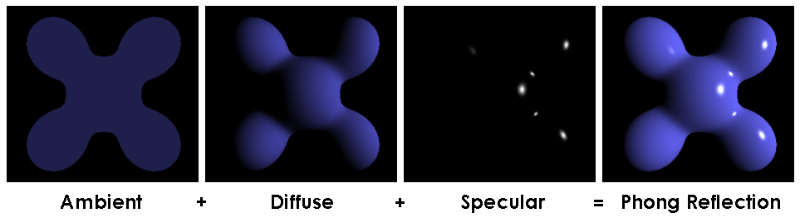
Phong Reflection Model by Wikipedia
The Phong reflection model provides an equation for computing the illumination on each point on a surface, I_p.

Phong Reflection Equation by Wikipedia
This equation may look complex, but I’ll explain each part of it! This equation is composed of three main parts: ambient, diffuse, and specular. The subscript, “m,” refers to the number of lights in our scene. We’ll assume just one light exists for now.
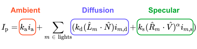
The first part represents the ambient light term. In GLSL code, it can be represented by the following:
1float k_a = 0.6; // a value of our choice, typically between zero and one
2vec3 i_a = vec3(0.7, 0.7, 0); // a color of our choice
3
4vec3 ambient = k_a * i_a;
The k_a value is the ambient reflection constant, the ratio of reflection of the ambient term present in all points in the scene rendered. The i_a value controls the ambient lighting and is sometimes computed as a sum of contributions from all light sources.
The second part of the Phong reflection equation represents the diffusion reflection term. In GLSL code, it can be represented by the following:
 1vec3 p = ro + rd * d; // point on surface found by ray marching
 2vec3 N = calcNormal(p); // surface normal
 3vec3 lightPosition = vec3(1, 1, 1);
 4vec3 L = normalize(lightPosition - p);
 5
 6float k_d = 0.5; // a value of our choice, typically between zero and one
 7vec3 dotLN = dot(L, N);
 8vec3 i_d = vec3(0.7, 0.5, 0); // a color of our choice
 9
10vec3 diffuse = k_d * dotLN * i_d;
The value, k_d, is the diffuse reflection constant, the ratio of reflection of the diffuse term of incoming light Lambertian reflectance. The value, dotLN, is the diffuse reflection we’ve been using in previous tutorials. It represents the Lambertian reflection. The value, i_d, is the intensity of a light source in your scene, defined by a color value in our case.
The third part of the Phong reflection equation is a bit more complex. It represents the specular reflection term. In real life, materials such as metals and polished surfaces have specular reflection that look brighter depending on the camera angle or where the viewer is facing the object. Therefore, this term is a function of the camera position in our scene.
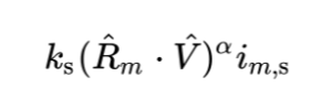
In GLSL code, it can be represented by the following:
 1vec3 p = ro + rd * d; // point on surface found by ray marching
 2vec3 N = calcNormal(p); // surface normal
 3vec3 lightPosition = vec3(1, 1, 1);
 4vec3 L = normalize(lightPosition - p);
 5
 6float k_s = 0.6; // a value of our choice, typically between zero and one
 7
 8vec3 R = reflect(L, N);
 9vec3 V = -rd; // direction pointing toward viewer (V) is just the negative of the ray direction
10
11vec3 dotRV = dot(R, V);
12vec3 i_s = vec3(1, 1, 1); // a color of our choice
13float alpha = 10.;
14
15vec3 specular = k_s * pow(dotRV, alpha) * i_s;
The value, k_s, is the specular reflection constant, the ratio of reflection of the specular term of incoming light.
The vector, R, is the direction that a perfectly reflected ray of light would take if it bounced off the surface.
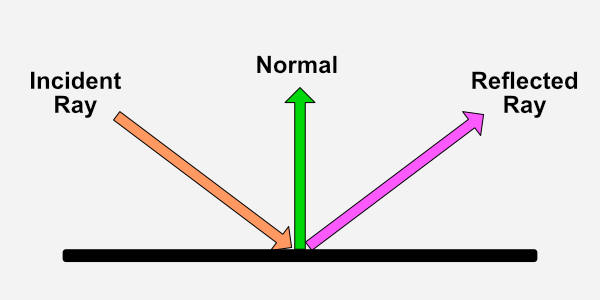
According to Wikipedia, the Phong reflection model calculates the reflected ray direction using the following formula.
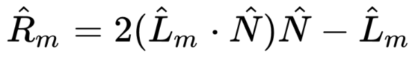
As mentioned previously, the subscript, “m,” refers to the number of lights in our scene. The little hat, ^, above each letter means we should use the normalized version of each vector. The vector, L, refers to the light direction. The vector, N refers to the surface normal.
GLSL provides a handly function called reflect that calculates the direction of the reflected ray from the incident ray for us. This function takes two parameters: the incident ray direction vector, and the normal vector.
Internally, the reflect function is equal to I - 2.0 * dot(N, I) * N where I is the incident ray direction and N is the normal vector. If we multiplied this equation by -1, we’d end up with the same equation as the reflection equation on Wikipedia. It’s all a matter of axes conventions.
The vector, V, in the code snippet for specular reflection represents the direction pointing towards the viewer or camera. We can set this equal to the negative of the ray direction, rd.
The alpha term is used to control the amount of “shininess” on the sphere. A lower value makes it appear shinier.
Putting it All Together
Let’s put everything we’ve learned so far together in our code. We’ll start with a simple sphere in our scene and use a lookat point for our camera model like we learned in Part 10.
 1const int MAX_MARCHING_STEPS = 255;
 2const float MIN_DIST = 0.0;
 3const float MAX_DIST = 100.0;
 4const float PRECISION = 0.001;
 5
 6float sdSphere(vec3 p, float r )
 7{
 8  return length(p) - r;
 9}
10
11float sdScene(vec3 p) {
12  return sdSphere(p, 1.);
13}
14
15float rayMarch(vec3 ro, vec3 rd) {
16  float depth = MIN_DIST;
17
18  for (int i = 0; i < MAX_MARCHING_STEPS; i++) {
19    vec3 p = ro + depth * rd;
20    float d = sdScene(p);
21    depth += d;
22    if (d < PRECISION || depth > MAX_DIST) break;
23  }
24
25  return depth;
26}
27
28vec3 calcNormal(vec3 p) {
29    vec2 e = vec2(1.0, -1.0) * 0.0005;
30    return normalize(
31      e.xyy * sdScene(p + e.xyy) +
32      e.yyx * sdScene(p + e.yyx) +
33      e.yxy * sdScene(p + e.yxy) +
34      e.xxx * sdScene(p + e.xxx));
35}
36
37mat3 camera(vec3 cameraPos, vec3 lookAtPoint) {
38	vec3 cd = normalize(lookAtPoint - cameraPos); // camera direction
39	vec3 cr = normalize(cross(vec3(0, 1, 0), cd)); // camera right
40	vec3 cu = normalize(cross(cd, cr)); // camera up
41
42	return mat3(-cr, cu, -cd);
43}
44
45void mainImage( out vec4 fragColor, in vec2 fragCoord )
46{
47  vec2 uv = (fragCoord-.5*iResolution.xy)/iResolution.y;
48  vec3 backgroundColor = vec3(0.835, 1, 1);
49  vec3 col = vec3(0);
50
51  vec3 lp = vec3(0); // lookat point (aka camera target)
52  vec3 ro = vec3(0, 0, 3);
53
54  vec3 rd = camera(ro, lp) * normalize(vec3(uv, -1)); // ray direction
55
56  float d = rayMarch(ro, rd);
57
58  if (d > MAX_DIST) {
59    col = backgroundColor;
60  } else {
61      vec3 p = ro + rd * d;
62      vec3 normal = calcNormal(p);
63      vec3 lightPosition = vec3(2, 2, 7);
64      vec3 lightDirection = normalize(lightPosition - p);
65
66      float diffuse = clamp(dot(lightDirection, normal), 0., 1.);
67
68      col = diffuse * vec3(0.7, 0.5, 0);
69  }
70
71  fragColor = vec4(col, 1.0);
72}
When you run the code, you should see a simple sphere in the scene with diffuse lighting.
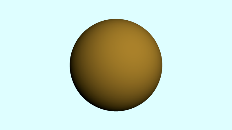
This is boring though. We want a shiny sphere! Currently, we’re only coloring the sphere based on diffuse lighting, or Lambertian reflection. Let’s add an ambient and specular component to complete the Phong reflection model. We’ll also adjust the light direction a bit, so we get a shine to appear on the top-right part of the sphere.
 1void mainImage( out vec4 fragColor, in vec2 fragCoord )
 2{
 3  vec2 uv = (fragCoord-.5*iResolution.xy)/iResolution.y;
 4  vec3 backgroundColor = vec3(0.835, 1, 1);
 5  vec3 col = vec3(0);
 6
 7  vec3 lp = vec3(0); // lookat point (aka camera target)
 8  vec3 ro = vec3(0, 0, 3);
 9
10  vec3 rd = camera(ro, lp) * normalize(vec3(uv, -1)); // ray direction
11
12  float d = rayMarch(ro, rd);
13
14  if (d > MAX_DIST) {
15    col = backgroundColor;
16  } else {
17      vec3 p = ro + rd * d; // point on surface found by ray marching
18      vec3 normal = calcNormal(p); // surface normal
19
20      // light
21      vec3 lightPosition = vec3(-8, -6, -5);
22      vec3 lightDirection = normalize(lightPosition - p);
23
24      // ambient
25      float k_a = 0.6;
26      vec3 i_a = vec3(0.7, 0.7, 0);
27      vec3 ambient = k_a * i_a;
28
29      // diffuse
30      float k_d = 0.5;
31      float dotLN = clamp(dot(lightDirection, normal), 0., 1.);
32      vec3 i_d = vec3(0.7, 0.5, 0);
33      vec3 diffuse = k_d * dotLN * i_d;
34
35      // specular
36      float k_s = 0.6;
37      float dotRV = clamp(dot(reflect(lightDirection, normal), -rd), 0., 1.);
38      vec3 i_s = vec3(1, 1, 1);
39      float alpha = 10.;
40      vec3 specular = k_s * pow(dotRV, alpha) * i_s;
41
42      // final sphere color
43      col = ambient + diffuse + specular;
44  }
45
46  fragColor = vec4(col, 1.0);
47}
Like before, we clamp the result of each dot product, so that the value is between zero and one. When we run the code, we should see the sphere glisten a bit on the top-right part of the sphere.
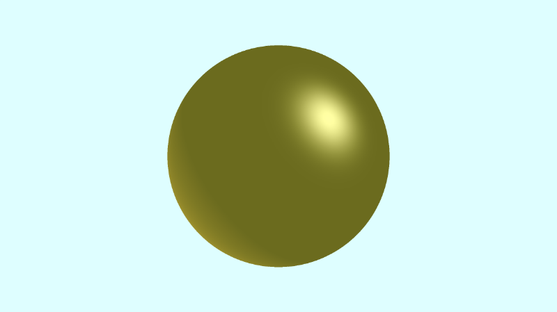
Multiple Lights
You may have noticed that the Phong reflection equation uses a summation for the diffuse and specular components. If you add more lights to the scene, then you’ll have a diffuse and specular component for each light.
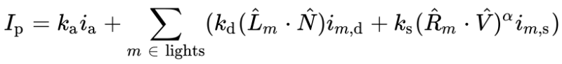
To make it easier to handle multiple lights, we’ll create a phong function. Since this scene is only coloring one object, we can place the reflection coefficients (k_a, k_d, k_s) and intensities in the phong function too.
  1const int MAX_MARCHING_STEPS = 255;
  2const float MIN_DIST = 0.0;
  3const float MAX_DIST = 100.0;
  4const float PRECISION = 0.001;
  5
  6float sdSphere(vec3 p, float r )
  7{
  8  return length(p) - r;
  9}
 10
 11float sdScene(vec3 p) {
 12  return sdSphere(p, 1.);
 13}
 14
 15float rayMarch(vec3 ro, vec3 rd) {
 16  float depth = MIN_DIST;
 17
 18  for (int i = 0; i < MAX_MARCHING_STEPS; i++) {
 19    vec3 p = ro + depth * rd;
 20    float d = sdScene(p);
 21    depth += d;
 22    if (d < PRECISION || depth > MAX_DIST) break;
 23  }
 24
 25  return depth;
 26}
 27
 28vec3 calcNormal(vec3 p) {
 29    vec2 e = vec2(1.0, -1.0) * 0.0005;
 30    return normalize(
 31      e.xyy * sdScene(p + e.xyy) +
 32      e.yyx * sdScene(p + e.yyx) +
 33      e.yxy * sdScene(p + e.yxy) +
 34      e.xxx * sdScene(p + e.xxx));
 35}
 36
 37mat3 camera(vec3 cameraPos, vec3 lookAtPoint) {
 38	vec3 cd = normalize(lookAtPoint - cameraPos); // camera direction
 39	vec3 cr = normalize(cross(vec3(0, 1, 0), cd)); // camera right
 40	vec3 cu = normalize(cross(cd, cr)); // camera up
 41
 42	return mat3(-cr, cu, -cd);
 43}
 44
 45vec3 phong(vec3 lightDir, vec3 normal, vec3 rd) {
 46  // ambient
 47  float k_a = 0.6;
 48  vec3 i_a = vec3(0.7, 0.7, 0);
 49  vec3 ambient = k_a * i_a;
 50
 51  // diffuse
 52  float k_d = 0.5;
 53  float dotLN = clamp(dot(lightDir, normal), 0., 1.);
 54  vec3 i_d = vec3(0.7, 0.5, 0);
 55  vec3 diffuse = k_d * dotLN * i_d;
 56
 57  // specular
 58  float k_s = 0.6;
 59  float dotRV = clamp(dot(reflect(lightDir, normal), -rd), 0., 1.);
 60  vec3 i_s = vec3(1, 1, 1);
 61  float alpha = 10.;
 62  vec3 specular = k_s * pow(dotRV, alpha) * i_s;
 63
 64  return ambient + diffuse + specular;
 65}
 66
 67void mainImage( out vec4 fragColor, in vec2 fragCoord )
 68{
 69  vec2 uv = (fragCoord-.5*iResolution.xy)/iResolution.y;
 70  vec3 backgroundColor = vec3(0.835, 1, 1);
 71  vec3 col = vec3(0);
 72
 73  vec3 lp = vec3(0); // lookat point (aka camera target)
 74  vec3 ro = vec3(0, 0, 3);
 75
 76  vec3 rd = camera(ro, lp) * normalize(vec3(uv, -1)); // ray direction
 77
 78  float d = rayMarch(ro, rd);
 79
 80  if (d > MAX_DIST) {
 81    col = backgroundColor;
 82  } else {
 83      vec3 p = ro + rd * d; // point on surface found by ray marching
 84      vec3 normal = calcNormal(p); // surface normal
 85
 86      // light #1
 87      vec3 lightPosition1 = vec3(-8, -6, -5);
 88      vec3 lightDirection1 = normalize(lightPosition1 - p);
 89      float lightIntensity1 = 0.6;
 90
 91      // light #2
 92      vec3 lightPosition2 = vec3(1, 1, 1);
 93      vec3 lightDirection2 = normalize(lightPosition2 - p);
 94      float lightIntensity2 = 0.7;
 95
 96      // final sphere color
 97      col = lightIntensity1 * phong(lightDirection1, normal, rd);
 98      col += lightIntensity2 * phong(lightDirection2, normal , rd);
 99  }
100
101  fragColor = vec4(col, 1.0);
102}
We can multiply the result of the phong function by light intensity values so that the sphere doesn’t appear too bright. When you run the code, your sphere should look shinier!!!
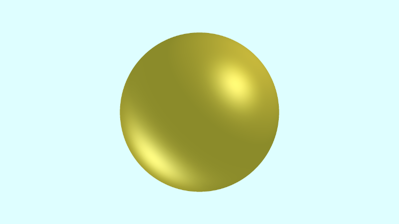
Coloring Multiple Objects
Placing all the reflection coefficients and intensities inside the phong function isn’t very practical. You could have multiple objects in your scene with different types of materials. Some objects could appear glossy and reflective while other objects have little to no specular reflectance.
It makes more sense to create materials that can be applied to one or more objects. Each material will have its own coefficients for ambient, diffuse, and specular components. We can create a struct for materials that will hold all the information needed for the Phong reflection model.
1struct Material {
2  vec3 ambientColor; // k_a * i_a
3  vec3 diffuseColor; // k_d * i_d
4  vec3 specularColor; // k_s * i_s
5  float alpha; // shininess
6};
Then, we could create another struct for each surface or object in the scene.
1struct Surface {
2  int id; // id of object
3  float sd; // signed distance value from SDF
4  Material mat; // material of object
5}
We’ll be creating a scene with a tiled floor and two spheres. First, we’ll create three materials. We’ll create a gold function that returns a gold material, a silver function that returns a silver material, and a checkerboard function that returns a checkerboard pattern. As you might expect, the checkerboard pattern won’t be very shiny, but the metals will!
 1Material gold() {
 2  vec3 aCol = 0.5 * vec3(0.7, 0.5, 0);
 3  vec3 dCol = 0.6 * vec3(0.7, 0.7, 0);
 4  vec3 sCol = 0.6 * vec3(1, 1, 1);
 5  float a = 5.;
 6
 7  return Material(aCol, dCol, sCol, a);
 8}
 9
10Material silver() {
11  vec3 aCol = 0.4 * vec3(0.8);
12  vec3 dCol = 0.5 * vec3(0.7);
13  vec3 sCol = 0.6 * vec3(1, 1, 1);
14  float a = 5.;
15
16  return Material(aCol, dCol, sCol, a);
17}
18
19Material checkerboard(vec3 p) {
20  vec3 aCol = vec3(1. + 0.7*mod(floor(p.x) + floor(p.z), 2.0)) * 0.3;
21  vec3 dCol = vec3(0.3);
22  vec3 sCol = vec3(0);
23  float a = 1.;
24
25  return Material(aCol, dCol, sCol, a);
26}
We’ll create a opUnion function that will act identical to the minWithColor function we used in previous tutorials.
1Surface opUnion(Surface obj1, Surface obj2) {
2  if (obj2.sd < obj1.sd) return obj2;
3  return obj1;
4}
Our scene will use the opUnion function to add the tiled floor and spheres to the scene:
1Surface scene(vec3 p) {
2  Surface sFloor = Surface(1, p.y + 1., checkerboard(p));
3  Surface sSphereGold = Surface(2, sdSphere(p - vec3(-2, 0, 0), 1.), gold());
4  Surface sSphereSilver = Surface(3, sdSphere(p - vec3(2, 0, 0), 1.), silver());
5
6  Surface co = opUnion(sFloor, sSphereGold);
7  co = opUnion(co, sSphereSilver);
8  return co;
9}
We’ll add a parameter to the phong function that accepts a Material. This material will hold all the color values we need for each component of the Phong reflection model.
 1vec3 phong(vec3 lightDir, vec3 normal, vec3 rd, Material mat) {
 2  // ambient
 3  vec3 ambient = mat.ambientColor;
 4
 5  // diffuse
 6  float dotLN = clamp(dot(lightDir, normal), 0., 1.);
 7  vec3 diffuse = mat.diffuseColor * dotLN;
 8
 9  // specular
10  float dotRV = clamp(dot(reflect(lightDir, normal), -rd), 0., 1.);
11  vec3 specular = mat.specularColor * pow(dotRV, mat.alpha);
12
13  return ambient + diffuse + specular;
14}
Inside the mainImage function, we can pass the material of the closest object to the phong function.
1col = lightIntensity1 * phong(lightDirection1, normal, rd, co.mat);
2col += lightIntensity2 * phong(lightDirection2, normal , rd, co.mat);
Putting this all together, we get the following code.
  1const int MAX_MARCHING_STEPS = 255;
  2const float MIN_DIST = 0.0;
  3const float MAX_DIST = 100.0;
  4const float PRECISION = 0.001;
  5
  6float sdSphere(vec3 p, float r )
  7{
  8  return length(p) - r;
  9}
 10
 11struct Material {
 12  vec3 ambientColor; // k_a * i_a
 13  vec3 diffuseColor; // k_d * i_d
 14  vec3 specularColor; // k_s * i_s
 15  float alpha; // shininess
 16};
 17
 18struct Surface {
 19  int id; // id of object
 20  float sd; // signed distance
 21  Material mat;
 22};
 23
 24Material gold() {
 25  vec3 aCol = 0.5 * vec3(0.7, 0.5, 0);
 26  vec3 dCol = 0.6 * vec3(0.7, 0.7, 0);
 27  vec3 sCol = 0.6 * vec3(1, 1, 1);
 28  float a = 5.;
 29
 30  return Material(aCol, dCol, sCol, a);
 31}
 32
 33Material silver() {
 34  vec3 aCol = 0.4 * vec3(0.8);
 35  vec3 dCol = 0.5 * vec3(0.7);
 36  vec3 sCol = 0.6 * vec3(1, 1, 1);
 37  float a = 5.;
 38
 39  return Material(aCol, dCol, sCol, a);
 40}
 41
 42Material checkerboard(vec3 p) {
 43  vec3 aCol = vec3(1. + 0.7*mod(floor(p.x) + floor(p.z), 2.0)) * 0.3;
 44  vec3 dCol = vec3(0.3);
 45  vec3 sCol = vec3(0);
 46  float a = 1.;
 47
 48  return Material(aCol, dCol, sCol, a);
 49}
 50
 51Surface opUnion(Surface obj1, Surface obj2) {
 52  if (obj2.sd < obj1.sd) return obj2;
 53  return obj1;
 54}
 55
 56Surface scene(vec3 p) {
 57  Surface sFloor = Surface(1, p.y + 1., checkerboard(p));
 58  Surface sSphereGold = Surface(2, sdSphere(p - vec3(-2, 0, 0), 1.), gold());
 59  Surface sSphereSilver = Surface(3, sdSphere(p - vec3(2, 0, 0), 1.), silver());
 60
 61  Surface co = opUnion(sFloor, sSphereGold); // closest object
 62  co = opUnion(co, sSphereSilver);
 63  return co;
 64}
 65
 66Surface rayMarch(vec3 ro, vec3 rd) {
 67  float depth = MIN_DIST;
 68  Surface co;
 69
 70  for (int i = 0; i < MAX_MARCHING_STEPS; i++) {
 71    vec3 p = ro + depth * rd;
 72    co = scene(p);
 73    depth += co.sd;
 74    if (co.sd < PRECISION || depth > MAX_DIST) break;
 75  }
 76
 77  co.sd = depth;
 78
 79  return co;
 80}
 81
 82vec3 calcNormal(vec3 p) {
 83    vec2 e = vec2(1.0, -1.0) * 0.0005;
 84    return normalize(
 85      e.xyy * scene(p + e.xyy).sd +
 86      e.yyx * scene(p + e.yyx).sd +
 87      e.yxy * scene(p + e.yxy).sd +
 88      e.xxx * scene(p + e.xxx).sd);
 89}
 90
 91mat3 camera(vec3 cameraPos, vec3 lookAtPoint) {
 92	vec3 cd = normalize(lookAtPoint - cameraPos); // camera direction
 93	vec3 cr = normalize(cross(vec3(0, 1, 0), cd)); // camera right
 94	vec3 cu = normalize(cross(cd, cr)); // camera up
 95
 96	return mat3(-cr, cu, -cd);
 97}
 98
 99vec3 phong(vec3 lightDir, vec3 normal, vec3 rd, Material mat) {
100  // ambient
101  vec3 ambient = mat.ambientColor;
102
103  // diffuse
104  float dotLN = clamp(dot(lightDir, normal), 0., 1.);
105  vec3 diffuse = mat.diffuseColor * dotLN;
106
107  // specular
108  float dotRV = clamp(dot(reflect(lightDir, normal), -rd), 0., 1.);
109  vec3 specular = mat.specularColor * pow(dotRV, mat.alpha);
110
111  return ambient + diffuse + specular;
112}
113
114void mainImage( out vec4 fragColor, in vec2 fragCoord )
115{
116  vec2 uv = (fragCoord-.5*iResolution.xy)/iResolution.y;
117  vec3 backgroundColor = mix(vec3(1, .341, .2), vec3(0, 1, 1), uv.y) * 1.6;
118  vec3 col = vec3(0);
119
120  vec3 lp = vec3(0); // lookat point (aka camera target)
121  vec3 ro = vec3(0, 0, 5);
122
123  vec3 rd = camera(ro, lp) * normalize(vec3(uv, -1)); // ray direction
124
125  Surface co = rayMarch(ro, rd); // closest object
126
127  if (co.sd > MAX_DIST) {
128    col = backgroundColor;
129  } else {
130      vec3 p = ro + rd * co.sd; // point on surface found by ray marching
131      vec3 normal = calcNormal(p); // surface normal
132
133      // light #1
134      vec3 lightPosition1 = vec3(-8, -6, -5);
135      vec3 lightDirection1 = normalize(lightPosition1 - p);
136      float lightIntensity1 = 0.9;
137
138      // light #2
139      vec3 lightPosition2 = vec3(1, 1, 1);
140      vec3 lightDirection2 = normalize(lightPosition2 - p);
141      float lightIntensity2 = 0.5;
142
143      // final color of object
144      col = lightIntensity1 * phong(lightDirection1, normal, rd, co.mat);
145      col += lightIntensity2 * phong(lightDirection2, normal , rd, co.mat);
146  }
147
148  fragColor = vec4(col, 1.0);
149}
When we run this code, we should see a golden sphere and silver sphere floating in front of a sunset. Gorgeous!
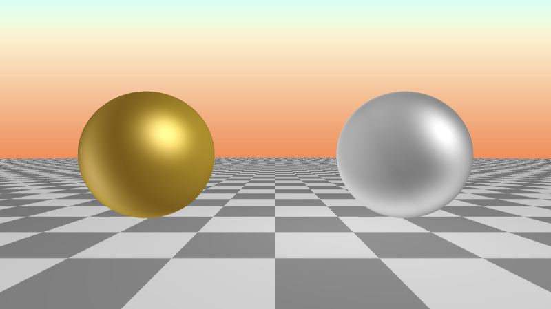
Conclusion
In this lesson, we learned how the Phong reflection model can really improve the look of our scene by adding a bit of glare or gloss to our objects. We also learned how to assign different materials to each object in the scene by using structs. Making shaders sure is fun! 😃
Resources
- Phong Reflection Model
- Lambertian Reflectance
- Khronos: Reflect
- Shadertoy: Phong Reflection Model
- Shadertoy: Gold and Silver Spheres
Tutorial Part 12 - Fresnel and Rim Lighting
转自:https://inspirnathan.com/posts/58-shadertoy-tutorial-part-12
Greetings, friends! Welcome to Part 12 of my Shadertoy tutorial series. In this tutorial, we’ll learn how to add rim lighting around a sphere using fresnel reflection.
Initial Setup
We’ll start with a basic ray marching template.
 1const int MAX_MARCHING_STEPS = 255;
 2const float MIN_DIST = 0.0;
 3const float MAX_DIST = 100.0;
 4const float PRECISION = 0.001;
 5
 6float sdSphere(vec3 p, float r )
 7{
 8  vec3 offset = vec3(0, 0, -2);
 9  return length(p - offset) - r;
10}
11
12float sdScene(vec3 p) {
13  return sdSphere(p, 1.);
14}
15
16float rayMarch(vec3 ro, vec3 rd) {
17  float depth = MIN_DIST;
18
19  for (int i = 0; i < MAX_MARCHING_STEPS; i++) {
20    vec3 p = ro + depth * rd;
21    float d = sdScene(p);
22    depth += d;
23    if (d < PRECISION || depth > MAX_DIST) break;
24  }
25
26  return depth;
27}
28
29vec3 calcNormal(vec3 p) {
30    vec2 e = vec2(1.0, -1.0) * 0.0005;
31    return normalize(
32      e.xyy * sdScene(p + e.xyy) +
33      e.yyx * sdScene(p + e.yyx) +
34      e.yxy * sdScene(p + e.yxy) +
35      e.xxx * sdScene(p + e.xxx));
36}
37
38void mainImage( out vec4 fragColor, in vec2 fragCoord )
39{
40  vec2 uv = (fragCoord-.5*iResolution.xy)/iResolution.y;
41  vec3 backgroundColor = vec3(0.1);
42  vec3 col = vec3(0);
43
44  vec3 ro = vec3(0, 0, 3);
45  vec3 rd = normalize(vec3(uv, -1));
46
47  float d = rayMarch(ro, rd);
48
49  if (d > MAX_DIST) {
50    col = backgroundColor;
51  } else {
52    vec3 p = ro + rd * d;
53    vec3 normal = calcNormal(p);
54    vec3 lightPosition = vec3(4, 4, 7);
55    vec3 lightDirection = normalize(lightPosition - p);
56
57    float diffuse = clamp(dot(normal, lightDirection), 0., 1.);
58    vec3 diffuseColor = vec3(0, 0.6, 1);
59
60    col = diffuse * diffuseColor;
61  }
62
63  fragColor = vec4(col, 1.0);
64}
When you run this code, you should see a blue sphere with only diffuse (Lambertian) reflection.
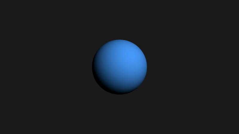
Fresnel Reflection
The Fresnel equations describe the reflection and transmission of light when it is incident on an interface between two different optical media. In simpler terms, this means that objects can be lit a bit differently when you look at them from grazing angles.
The term, optical media, refers to the type of material light passes through. Different materials tend to have different refractive indices which makes it appear that light is bending.
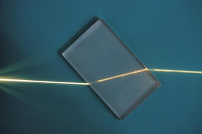
Refraction by Wikipedia
Air is a type of medium. It typically has an index of refraction of about 1.000293. Materials such as diamonds have a high index of refraction. Diamond has an index of refraction of 2.417. A high index of refraction means light will appear to bend even more.
The Fresnel equations can get pretty complicated. For computer graphics, you will typically see people use the Schlick’s approximation for approximating the Fresnel contribution of reflection.
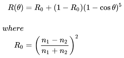
Schlick’s approximation by Wikipedia
The above equation calculates the Fresnel contribution to reflection, R where R0 is the reflection coefficient for light incoming parallel to the normal (typically when θ equals zero).
The value of cos θ is equal to the dot product between the surface normal and the direction the incident light is coming from. In our code, however, we’ll use the ray direction, rd.
For the purposes of our examples, we will assume that the refractive index of air and the sphere are both equal to one. This will help simplify our calculations. This means that R0 is equal to zero.
n1 = 1
n2 = 1

R0 = ((n1 - n2)/(n1 + n2)) ^ 2
R0 = ((1 - 1)/(1 + 1)) ^ 2
R0 = 0
With R0 equal to zero, we can simplify the Fresnel reflection equation even more.
R = R0 + (1 - R0)(1 - cosθ)^5

Since R0 = 0,
R = (1 - cosθ)^5
In GLSL code, this can be written as:
1float fresnel = pow(1. - dot(normal, -rd), 5.);However, we clamp the values to make sure we keep the range between zero and one. We also use -rd. If you used positive rd, then you might not see the color only being applied to the rim of the sphere.
1float fresnel = pow(clamp(1. - dot(normal, -rd), 0., 1.), 5.);We can multiply this fresnel value by a color value, so we can apply a colored rim around our blue sphere. Below is the finished code:
 1const int MAX_MARCHING_STEPS = 255;
 2const float MIN_DIST = 0.0;
 3const float MAX_DIST = 100.0;
 4const float PRECISION = 0.001;
 5
 6float sdSphere(vec3 p, float r )
 7{
 8  vec3 offset = vec3(0, 0, -2);
 9  return length(p - offset) - r;
10}
11
12float sdScene(vec3 p) {
13  return sdSphere(p, 1.);
14}
15
16float rayMarch(vec3 ro, vec3 rd) {
17  float depth = MIN_DIST;
18
19  for (int i = 0; i < MAX_MARCHING_STEPS; i++) {
20    vec3 p = ro + depth * rd;
21    float d = sdScene(p);
22    depth += d;
23    if (d < PRECISION || depth > MAX_DIST) break;
24  }
25
26  return depth;
27}
28
29vec3 calcNormal(vec3 p) {
30    vec2 e = vec2(1.0, -1.0) * 0.0005;
31    return normalize(
32      e.xyy * sdScene(p + e.xyy) +
33      e.yyx * sdScene(p + e.yyx) +
34      e.yxy * sdScene(p + e.yxy) +
35      e.xxx * sdScene(p + e.xxx));
36}
37
38void mainImage( out vec4 fragColor, in vec2 fragCoord )
39{
40  vec2 uv = (fragCoord-.5*iResolution.xy)/iResolution.y;
41  vec3 backgroundColor = vec3(0.1);
42  vec3 col = vec3(0);
43
44  vec3 ro = vec3(0, 0, 3);
45  vec3 rd = normalize(vec3(uv, -1));
46
47  float d = rayMarch(ro, rd);
48
49  if (d > MAX_DIST) {
50    col = backgroundColor;
51  } else {
52    vec3 p = ro + rd * d;
53    vec3 normal = calcNormal(p);
54    vec3 lightPosition = vec3(4, 4, 7);
55    vec3 lightDirection = normalize(lightPosition - p);
56
57    float diffuse = clamp(dot(normal, lightDirection), 0., 1.);
58    vec3 diffuseColor = vec3(0, 0.6, 1);
59
60    float fresnel = pow(clamp(1. - dot(normal, -rd), 0., 1.), 5.);
61    vec3 rimColor = vec3(1, 1, 1);
62
63    col = diffuse * diffuseColor + fresnel * rimColor; // add the fresnel contribution
64  }
65
66  fragColor = vec4(col, 1.0);
67}
If you run this code, you should see a thin white rim of our blue sphere. This simulates the effect of light hitting a grazing angle of our sphere.
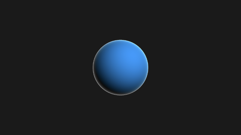
You can play around with the exponent and the rim color to get a “force field” like effect.
1float fresnel = pow(clamp(1. - dot(normal, -rd), 0., 1.), 0.5);
2vec3 rimColor = vec3(1, 0, 1);
3
4col = diffuse * diffuseColor + fresnel * rimColor;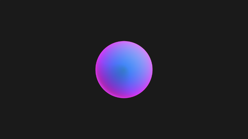
Conclusion
In this article we learned how to add rim lighting around objects by applying fresnel reflection. If you’re dealing with objects that mimic glass or plastic, then adding fresnel can help make them a bit more realistic.
Resources
- Wikipedia: Fresnel Equations
- Wikipedia: Medium (optics)
- Wikipedia: Refractive Index
- Wikipedia: Schlick’s Approximation
- Shadertoy: Sphere Rim Lighting with Fresnel
Tutorial Part 13 - Shadows
转自:https://inspirnathan.com/posts/59-shadertoy-tutorial-part-13
Greetings, friends! Welcome to Part 13 of my Shadertoy tutorial series. In this tutorial, we’ll learn how to add shadows to our 3D scene.
Initial Setup
Our starting code for this tutorial is going to be a bit different this time. We’re going to go back to rendering scenes with just one color and we’ll go back to using a basic camera with no lookat point. I’ve also made the rayMarch function a bit simpler. It accepts two parameters instead of four. We weren’t really using the last two parameters anyways.
 1const int MAX_MARCHING_STEPS = 255;
 2const float MIN_DIST = 0.0;
 3const float MAX_DIST = 100.0;
 4const float PRECISION = 0.001;
 5const float EPSILON = 0.0005;
 6
 7float sdSphere(vec3 p, float r, vec3 offset)
 8{
 9  return length(p - offset) - r;
10}
11
12float sdFloor(vec3 p) {
13  return p.y + 1.;
14}
15
16float scene(vec3 p) {
17  float co = min(sdSphere(p, 1., vec3(0, 0, -2)), sdFloor(p));
18  return co;
19}
20
21float rayMarch(vec3 ro, vec3 rd) {
22  float depth = MIN_DIST;
23  float d; // distance ray has travelled
24
25  for (int i = 0; i < MAX_MARCHING_STEPS; i++) {
26    vec3 p = ro + depth * rd;
27    d = scene(p);
28    depth += d;
29    if (d < PRECISION || depth > MAX_DIST) break;
30  }
31
32  d = depth;
33
34  return d;
35}
36
37vec3 calcNormal(in vec3 p) {
38    vec2 e = vec2(1, -1) * EPSILON;
39    return normalize(
40      e.xyy * scene(p + e.xyy) +
41      e.yyx * scene(p + e.yyx) +
42      e.yxy * scene(p + e.yxy) +
43      e.xxx * scene(p + e.xxx));
44}
45
46void mainImage( out vec4 fragColor, in vec2 fragCoord )
47{
48  vec2 uv = (fragCoord-.5*iResolution.xy)/iResolution.y;
49  vec3 backgroundColor = vec3(0);
50
51  vec3 col = vec3(0);
52  vec3 ro = vec3(0, 0, 3); // ray origin that represents camera position
53  vec3 rd = normalize(vec3(uv, -1)); // ray direction
54
55  float sd = rayMarch(ro, rd); // signed distance value to closest object
56
57  if (sd > MAX_DIST) {
58    col = backgroundColor; // ray didn't hit anything
59  } else {
60    vec3 p = ro + rd * sd; // point discovered from ray marching
61    vec3 normal = calcNormal(p); // surface normal
62
63    vec3 lightPosition = vec3(cos(iTime), 2, sin(iTime));
64    vec3 lightDirection = normalize(lightPosition - p);
65
66    float dif = clamp(dot(normal, lightDirection), 0., 1.); // diffuse reflection clamped between zero and one
67
68    col = vec3(dif);
69  }
70
71  fragColor = vec4(col, 1.0);
72}
After running the code, we should see a very basic 3D scene with a sphere, a floor, and diffuse reflection. The color from the diffuse reflection will be shades of gray between black and white.
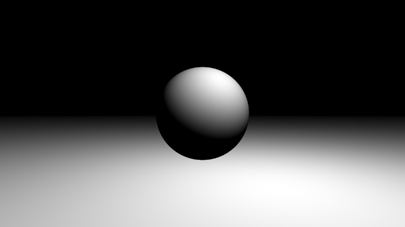
Basic Shadows
Let’s start with learning how to add very simple shadows. Before we start coding, let’s look at the image below to visualize how the algorithm will work.
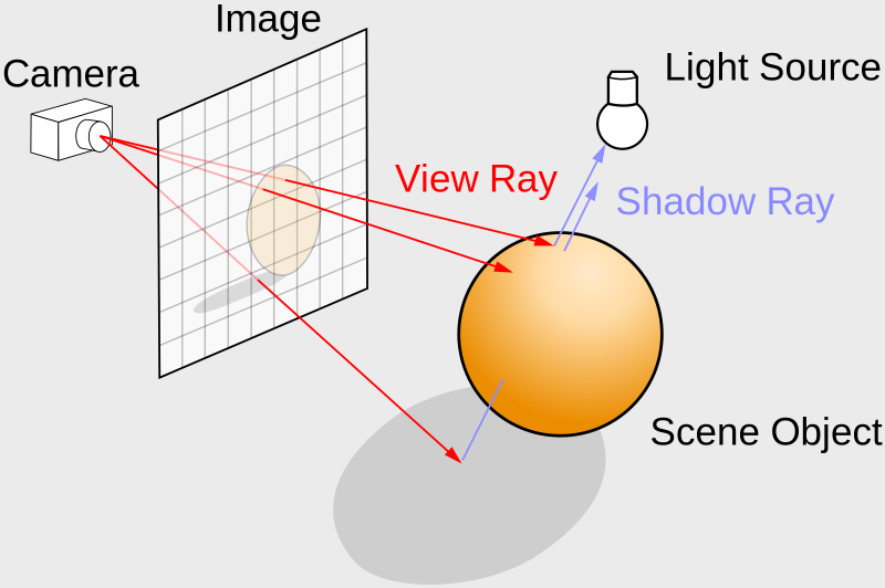
Ray tracing diagram by Wikipedia
Our rayMarch function implements the ray marching algorithm. We currently use it for discovering a point in the scene that hits the nearest object or surface. However, we can use it a second time to generate a new ray and point this ray toward our light source in the scene. In the image above, there are “shadow rays” that are casted toward the light source from the floor.
In our code, we will perform ray marching a second time, where the new ray origin is equal to p, the point on the sphere or floor we discovered from the first ray marching step. The new ray direction will be equal to lightDirection. In our code, it’s as simple as adding three lines underneath the diffuse reflection calculation.
1float dif = clamp(dot(normal, lightDirection), 0., 1.); // diffuse reflection clamped between zero and one
2
3vec3 newRayOrigin = p;
4float shadowRayLength = rayMarch(newRayOrigin, lightDirection); // cast shadow ray to the light source
5if (shadowRayLength < length(lightPosition - newRayOrigin)) dif *= 0.; // if the shadow ray hits the sphere, set the diffuse reflection to zero, simulating a shadow
However, when you run this code, the screen will appear almost completely black. What’s going on? During the first ray march loop, we fire off rays from the camera. If our ray hits a point, p, that is closer to the floor than the sphere, then the signed distance value will equal to the length from the camera to the floor.
When we use this same p value in the second ray march loop, we already know it’s closer to the floor than the surface of the sphere. Therefore almost everything will seem like it’s in the shadow, causing the screen to go black. We need to choose a value very close to p during the second ray march step, so we don’t have this issue occurring.
A common approach is to add the surface normal, multiplied by a tiny value, to the value of p, so we get a neighboring point. We will use the PRECISION variable as the tiny value that will slightly nudge p to a neighboring point.
1vec3 newRayOrigin = p + normal * PRECISION;When you run the code, you should now see a shadow appear below the sphere. However, there’s a strange artifact near the center of the sphere.
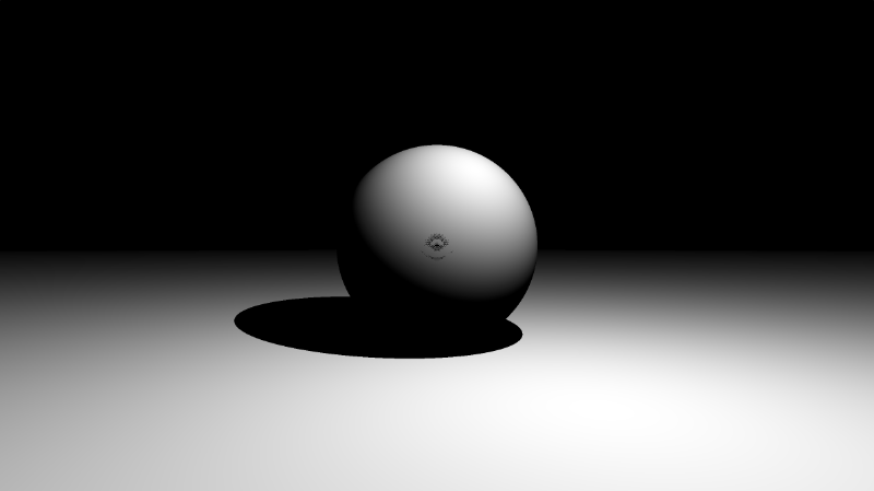
We can multiply the precision value by two to make it go away.
1vec3 newRayOrigin = p + normal * PRECISION * 2.;
When adding shadows to your scene, you may need to keep adjusting newRayOrigin by multiplying by different factors to see what works. Making realistic shadows is not an easy task, and you may find yourself playing around with values until it looks good.
You finished code should look like the following:
 1const int MAX_MARCHING_STEPS = 255;
 2const float MIN_DIST = 0.0;
 3const float MAX_DIST = 100.0;
 4const float PRECISION = 0.001;
 5const float EPSILON = 0.0005;
 6
 7float sdSphere(vec3 p, float r, vec3 offset)
 8{
 9  return length(p - offset) - r;
10}
11
12float sdFloor(vec3 p) {
13  return p.y + 1.;
14}
15
16float scene(vec3 p) {
17  float co = min(sdSphere(p, 1., vec3(0, 0, -2)), sdFloor(p));
18  return co;
19}
20
21float rayMarch(vec3 ro, vec3 rd) {
22  float depth = MIN_DIST;
23  float d; // distance ray has travelled
24
25  for (int i = 0; i < MAX_MARCHING_STEPS; i++) {
26    vec3 p = ro + depth * rd;
27    d = scene(p);
28    depth += d;
29    if (d < PRECISION || depth > MAX_DIST) break;
30  }
31
32  d = depth;
33
34  return d;
35}
36
37vec3 calcNormal(in vec3 p) {
38    vec2 e = vec2(1, -1) * EPSILON;
39    return normalize(
40      e.xyy * scene(p + e.xyy) +
41      e.yyx * scene(p + e.yyx) +
42      e.yxy * scene(p + e.yxy) +
43      e.xxx * scene(p + e.xxx));
44}
45
46void mainImage( out vec4 fragColor, in vec2 fragCoord )
47{
48  vec2 uv = (fragCoord-.5*iResolution.xy)/iResolution.y;
49  vec3 backgroundColor = vec3(0);
50
51  vec3 col = vec3(0);
52  vec3 ro = vec3(0, 0, 3); // ray origin that represents camera position
53  vec3 rd = normalize(vec3(uv, -1)); // ray direction
54
55  float sd = rayMarch(ro, rd); // signed distance value to closest object
56
57  if (sd > MAX_DIST) {
58    col = backgroundColor; // ray didn't hit anything
59  } else {
60    vec3 p = ro + rd * sd; // point discovered from ray marching
61    vec3 normal = calcNormal(p); // surface normal
62
63    vec3 lightPosition = vec3(cos(iTime), 2, sin(iTime));
64    vec3 lightDirection = normalize(lightPosition - p);
65
66    float dif = clamp(dot(normal, lightDirection), 0., 1.); // diffuse reflection clamped between zero and one
67
68    vec3 newRayOrigin = p + normal * PRECISION * 2.;
69    float shadowRayLength = rayMarch(newRayOrigin, lightDirection);
70    if (shadowRayLength < length(lightPosition - newRayOrigin)) dif *= 0.;
71
72    col = vec3(dif);
73  }
74
75  fragColor = vec4(col, 1.0);
76}
Adding Shadows to Colored Scenes
Using the same technique, we can apply shadows to the colored scenes we’ve been working with in the past few tutorials.
 1const int MAX_MARCHING_STEPS = 255;
 2const float MIN_DIST = 0.0;
 3const float MAX_DIST = 100.0;
 4const float PRECISION = 0.001;
 5const float EPSILON = 0.0005;
 6
 7struct Surface {
 8    float sd; // signed distance value
 9    vec3 col; // color
10};
11
12Surface sdFloor(vec3 p, vec3 col) {
13  float d = p.y + 1.;
14  return Surface(d, col);
15}
16
17Surface sdSphere(vec3 p, float r, vec3 offset, vec3 col) {
18  p = (p - offset);
19  float d = length(p) - r;
20  return Surface(d, col);
21}
22
23Surface opUnion(Surface obj1, Surface obj2) {
24  if (obj2.sd < obj1.sd) return obj2;
25  return obj1;
26}
27
28Surface scene(vec3 p) {
29  vec3 floorColor = vec3(0.1 + 0.7 * mod(floor(p.x) + floor(p.z), 2.0));
30  Surface co = sdFloor(p, floorColor);
31  co = opUnion(co, sdSphere(p, 1., vec3(0, 0, -2), vec3(1, 0, 0)));
32  return co;
33}
34
35Surface rayMarch(vec3 ro, vec3 rd) {
36  float depth = MIN_DIST;
37  Surface co; // closest object
38
39  for (int i = 0; i < MAX_MARCHING_STEPS; i++) {
40    vec3 p = ro + depth * rd;
41    co = scene(p);
42    depth += co.sd;
43    if (co.sd < PRECISION || depth > MAX_DIST) break;
44  }
45
46  co.sd = depth;
47
48  return co;
49}
50
51vec3 calcNormal(in vec3 p) {
52    vec2 e = vec2(1, -1) * EPSILON;
53    return normalize(
54      e.xyy * scene(p + e.xyy).sd +
55      e.yyx * scene(p + e.yyx).sd +
56      e.yxy * scene(p + e.yxy).sd +
57      e.xxx * scene(p + e.xxx).sd);
58}
59
60void mainImage( out vec4 fragColor, in vec2 fragCoord )
61{
62  vec2 uv = (fragCoord-.5*iResolution.xy)/iResolution.y;
63  vec3 backgroundColor = vec3(0.835, 1, 1);
64
65  vec3 col = vec3(0);
66  vec3 ro = vec3(0, 0, 3); // ray origin that represents camera position
67  vec3 rd = normalize(vec3(uv, -1)); // ray direction
68
69  Surface co = rayMarch(ro, rd); // closest object
70
71  if (co.sd > MAX_DIST) {
72    col = backgroundColor; // ray didn't hit anything
73  } else {
74    vec3 p = ro + rd * co.sd; // point discovered from ray marching
75    vec3 normal = calcNormal(p);
76
77    vec3 lightPosition = vec3(cos(iTime), 2, sin(iTime));
78    vec3 lightDirection = normalize(lightPosition - p);
79
80    float dif = clamp(dot(normal, lightDirection), 0., 1.); // diffuse reflection
81
82    vec3 newRayOrigin = p + normal * PRECISION * 2.;
83    float shadowRayLength = rayMarch(newRayOrigin, lightDirection).sd; // cast shadow ray to the light source
84    if (shadowRayLength < length(lightPosition - newRayOrigin)) dif *= 0.0; // shadow
85
86    col = dif * co.col;
87
88  }
89
90  fragColor = vec4(col, 1.0); // Output to screen
91}
If you run this code, you should see a red sphere with a moving light source (and therefore “moving” shadow), but the entire scene appears a bit too dark.
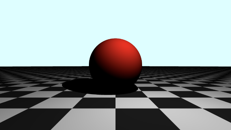
Gamma Correction
We can apply a bit of gamma correction to make the darker colors brighter. We’ll add this line right before we output the final color to the screen.
1col = pow(col, vec3(1.0/2.2)); // Gamma correctionYour mainImage function should now look like the following:
 1void mainImage( out vec4 fragColor, in vec2 fragCoord )
 2{
 3  vec2 uv = (fragCoord-.5*iResolution.xy)/iResolution.y;
 4  vec3 backgroundColor = vec3(0.835, 1, 1);
 5
 6  vec3 col = vec3(0);
 7  vec3 ro = vec3(0, 0, 3); // ray origin that represents camera position
 8  vec3 rd = normalize(vec3(uv, -1)); // ray direction
 9
10  Surface co = rayMarch(ro, rd); // closest object
11
12  if (co.sd > MAX_DIST) {
13    col = backgroundColor; // ray didn't hit anything
14  } else {
15    vec3 p = ro + rd * co.sd; // point discovered from ray marching
16    vec3 normal = calcNormal(p);
17
18    vec3 lightPosition = vec3(cos(iTime), 2, sin(iTime));
19    vec3 lightDirection = normalize(lightPosition - p);
20
21    float dif = clamp(dot(normal, lightDirection), 0., 1.); // diffuse reflection
22
23    vec3 newRayOrigin = p + normal * PRECISION * 2.;
24    float shadowRayLength = rayMarch(newRayOrigin, lightDirection).sd; // cast shadow ray to the light source
25    if (shadowRayLength < length(lightPosition - newRayOrigin)) dif *= 0.; // shadow
26
27    col = dif * co.col;
28
29  }
30
31  col = pow(col, vec3(1.0/2.2)); // Gamma correction
32  fragColor = vec4(col, 1.0); // Output to screen
33}
When you run the code, you should see the entire scene appear brighter.
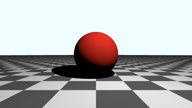
The shadow seems a bit too dark still. We can lighten it by adjusting how much we should scale the diffuse reflection by. Currently, we’re setting the diffuse reflection color of the floor and sphere to zero when we calculate which points lie in the shadow.
We can change the “scaling factor” to 0.2 instead:
1if (shadowRayLength < length(lightPosition - newRayOrigin)) dif *= 0.2; // shadowNow the shadow looks a bit better, and you can see the diffuse color of the floor through the shadow.
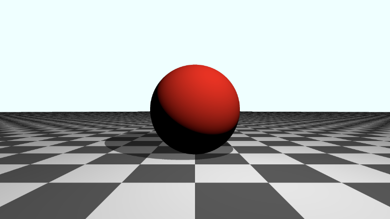
Soft Shadows
In real life, shadows tend to have multiple parts, including an umbra, penumbra, and antumbra. We can add a “soft shadow” that tries to copy shadows in real life by using algorithms found on Inigo Quilez’s website.
Below is an implementation of the “soft shadow” function found in the popular Shadertoy shader, Raymarching Primitives Commented. I have made adjustments to make it compatible with our code.
 1float softShadow(vec3 ro, vec3 rd, float mint, float tmax) {
 2  float res = 1.0;
 3  float t = mint;
 4
 5  for(int i = 0; i < 16; i++) {
 6    float h = scene(ro + rd * t).sd;
 7      res = min(res, 8.0*h/t);
 8      t += clamp(h, 0.02, 0.10);
 9      if(h < 0.001 || t > tmax) break;
10  }
11
12  return clamp( res, 0.0, 1.0 );
13}
In our mainImage function, we can remove the “hard shadow” code and replace it with the “soft shadow” implementation.
1float softShadow = clamp(softShadow(p, lightDirection, 0.02, 2.5), 0.1, 1.0);
2col = dif * co.col * softShadow;
We can clamp the shadow between 0.1 and 1.0 to lighten the shadow a bit, so it’s not too dark.
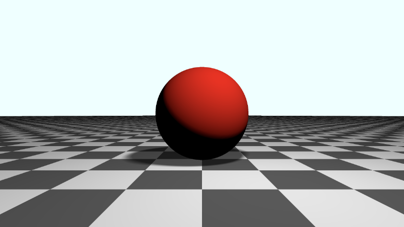
Notice the edges of the soft shadow. It’s a smoother transition between the shadow and normal floor color.
Applying Fog
You may have noticed that the color of the sphere not facing the light appears too dark still. We can attempt to lighten it by adding 0.5 to the diffuse reflection, dif.
1float dif = clamp(dot(normal, lightDirection), 0., 1.) + 0.5; // diffuse reflectionWhen you run the code, you’ll see that the sphere appears a bit brighter, but the back of the floor in the distance looks kinda weird.
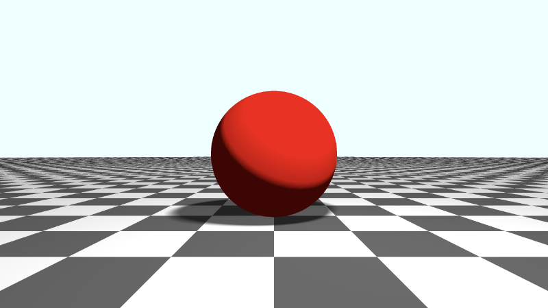
You may commonly see people hide any irregularities of the background by applying fog. Let’s apply fog right before the gamma correction.
1col = mix(col, backgroundColor, 1.0 - exp(-0.0002 * co.sd * co.sd * co.sd)); // fogNow, the scene looks a bit more realistic!
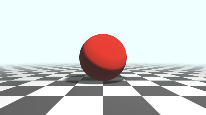
You can find the finished code below:
  1/* The MIT License
  2** Copyright © 2022 Nathan Vaughn
  3** Permission is hereby granted, free of charge, to any person obtaining a copy of this software and associated documentation files (the "Software"), to deal in the Software without restriction, including without limitation the rights to use, copy, modify, merge, publish, distribute, sublicense, and/or sell copies of the Software, and to permit persons to whom the Software is furnished to do so, subject to the following conditions: The above copyright notice and this permission notice shall be included in all copies or substantial portions of the Software. THE SOFTWARE IS PROVIDED "AS IS", WITHOUT WARRANTY OF ANY KIND, EXPRESS OR IMPLIED, INCLUDING BUT NOT LIMITED TO THE WARRANTIES OF MERCHANTABILITY, FITNESS FOR A PARTICULAR PURPOSE AND NONINFRINGEMENT. IN NO EVENT SHALL THE AUTHORS OR COPYRIGHT HOLDERS BE LIABLE FOR ANY CLAIM, DAMAGES OR OTHER LIABILITY, WHETHER IN AN ACTION OF CONTRACT, TORT OR OTHERWISE, ARISING FROM, OUT OF OR IN CONNECTION WITH THE SOFTWARE OR THE USE OR OTHER DEALINGS IN THE SOFTWARE.
  4**
  5** Example on how to create a shadow, apply gamma correction, and apply fog.
  6** Visit my tutorial to learn more: https://inspirnathan.com/posts/63-shadertoy-tutorial-part-16/
  7**
  8** Resources/Credit:
  9** Primitive SDFs: https://iquilezles.org/articles/distfunctions
 10** Soft Shadows: https://iquilezles.org/articles/rmshadows/
 11*/
 12
 13const int MAX_MARCHING_STEPS = 255;
 14const float MIN_DIST = 0.0;
 15const float MAX_DIST = 100.0;
 16const float PRECISION = 0.001;
 17const float EPSILON = 0.0005;
 18
 19struct Surface {
 20    float sd; // signed distance value
 21    vec3 col; // color
 22};
 23
 24Surface sdFloor(vec3 p, vec3 col) {
 25  float d = p.y + 1.;
 26  return Surface(d, col);
 27}
 28
 29Surface sdSphere(vec3 p, float r, vec3 offset, vec3 col) {
 30  p = (p - offset);
 31  float d = length(p) - r;
 32  return Surface(d, col);
 33}
 34
 35Surface opUnion(Surface obj1, Surface obj2) {
 36  if (obj2.sd < obj1.sd) return obj2;
 37  return obj1;
 38}
 39
 40Surface scene(vec3 p) {
 41  vec3 floorColor = vec3(0.1 + 0.7*mod(floor(p.x) + floor(p.z), 2.0));
 42  Surface co = sdFloor(p, floorColor);
 43  co = opUnion(co, sdSphere(p, 1., vec3(0, 0, -2), vec3(1, 0, 0)));
 44  return co;
 45}
 46
 47Surface rayMarch(vec3 ro, vec3 rd) {
 48  float depth = MIN_DIST;
 49  Surface co; // closest object
 50
 51  for (int i = 0; i < MAX_MARCHING_STEPS; i++) {
 52    vec3 p = ro + depth * rd;
 53    co = scene(p);
 54    depth += co.sd;
 55    if (co.sd < PRECISION || depth > MAX_DIST) break;
 56  }
 57
 58  co.sd = depth;
 59
 60  return co;
 61}
 62
 63vec3 calcNormal(in vec3 p) {
 64    vec2 e = vec2(1, -1) * EPSILON;
 65    return normalize(
 66      e.xyy * scene(p + e.xyy).sd +
 67      e.yyx * scene(p + e.yyx).sd +
 68      e.yxy * scene(p + e.yxy).sd +
 69      e.xxx * scene(p + e.xxx).sd);
 70}
 71
 72float softShadow(vec3 ro, vec3 rd, float mint, float tmax) {
 73  float res = 1.0;
 74  float t = mint;
 75
 76  for(int i = 0; i < 16; i++) {
 77    float h = scene(ro + rd * t).sd;
 78      res = min(res, 8.0*h/t);
 79      t += clamp(h, 0.02, 0.10);
 80      if(h < 0.001 || t > tmax) break;
 81  }
 82
 83  return clamp( res, 0.0, 1.0 );
 84}
 85
 86void mainImage( out vec4 fragColor, in vec2 fragCoord )
 87{
 88  vec2 uv = (fragCoord-.5*iResolution.xy)/iResolution.y;
 89  vec3 backgroundColor = vec3(0.835, 1, 1);
 90
 91  vec3 col = vec3(0);
 92  vec3 ro = vec3(0, 0, 3); // ray origin that represents camera position
 93  vec3 rd = normalize(vec3(uv, -1)); // ray direction
 94
 95  Surface co = rayMarch(ro, rd); // closest object
 96
 97  if (co.sd > MAX_DIST) {
 98    col = backgroundColor; // ray didn't hit anything
 99  } else {
100    vec3 p = ro + rd * co.sd; // point discovered from ray marching
101    vec3 normal = calcNormal(p);
102
103    vec3 lightPosition = vec3(cos(iTime), 2, sin(iTime));
104    vec3 lightDirection = normalize(lightPosition - p);
105
106    float dif = clamp(dot(normal, lightDirection), 0., 1.) + 0.5; // diffuse reflection
107
108    float softShadow = clamp(softShadow(p, lightDirection, 0.02, 2.5), 0.1, 1.0);
109
110    col = dif * co.col * softShadow;
111  }
112
113  col = mix(col, backgroundColor, 1.0 - exp(-0.0002 * co.sd * co.sd * co.sd)); // fog
114  col = pow(col, vec3(1.0/2.2)); // Gamma correction
115  fragColor = vec4(col, 1.0); // Output to screen
116}
Conclusion
In this tutorial, you learned how to apply “hard shadows,” “soft shadows,” gamma correction, and fog. As we’ve seen, adding shadows can be a bit tricky. In this tutorial, I discussed how to add shadows to a scene with only diffuse reflection, but the same principles apply to scenes with other types of reflections as well. You need to make sure you understand how your scene is lit and anticipate how shadows will impact the colors in your scene. What I’ve mentioned in this article is just one way of adding shadows to your scene. As you dive into the code of various shaders on Shadertoy, you’ll find completely different ways lighting is set up in the scene.
Resources
- Sphere with Shadow and Fog
- YouTube: Ray Marching For Dummies
- Wikipedia: Gamma Correction
- Shadertoy: Raymarching Primitives
- Shadertoy: Raymarching Primitives Commented
- Fog
- Outdoors Lighting
Tutorial Part 14 - SDF Operations
转自:https://inspirnathan.com/posts/60-shadertoy-tutorial-part-14
Greetings, friends! Welcome to Part 14 of my Shadertoy tutorial series! Have you ever wondered how people draw complex shapes and scenes in Shadertoy? We learned how to make spheres and cubes, but what about more complicated objects? In this tutorial, we’ll learn how to use SDF operations popularized by the talented Inigo Quilez, one of the co-creators of Shadertoy!
Initial Setup
Below, I have created a ray marching template that may prove useful for you if you plan on developing 3D models using Shadertoy and ray marching. We will start with this code for this tutorial.
 1const int MAX_MARCHING_STEPS = 255;
 2const float MIN_DIST = 0.0;
 3const float MAX_DIST = 100.0;
 4const float PRECISION = 0.001;
 5const float EPSILON = 0.0005;
 6const float PI = 3.14159265359;
 7const vec3 COLOR_BACKGROUND = vec3(.741, .675, .82);
 8const vec3 COLOR_AMBIENT = vec3(0.42, 0.20, 0.1);
 9
10mat2 rotate2d(float theta) {
11  float s = sin(theta), c = cos(theta);
12  return mat2(c, -s, s, c);
13}
14
15float sdSphere(vec3 p, float r, vec3 offset)
16{
17  return length(p - offset) - r;
18}
19
20float scene(vec3 p) {
21  return sdSphere(p, 1., vec3(0, 0, 0));
22}
23
24float rayMarch(vec3 ro, vec3 rd) {
25  float depth = MIN_DIST;
26  float d; // distance ray has travelled
27
28  for (int i = 0; i < MAX_MARCHING_STEPS; i++) {
29    vec3 p = ro + depth * rd;
30    d = scene(p);
31    depth += d;
32    if (d < PRECISION || depth > MAX_DIST) break;
33  }
34
35  d = depth;
36
37  return d;
38}
39
40vec3 calcNormal(in vec3 p) {
41    vec2 e = vec2(1, -1) * EPSILON;
42    return normalize(
43      e.xyy * scene(p + e.xyy) +
44      e.yyx * scene(p + e.yyx) +
45      e.yxy * scene(p + e.yxy) +
46      e.xxx * scene(p + e.xxx));
47}
48
49mat3 camera(vec3 cameraPos, vec3 lookAtPoint) {
50	vec3 cd = normalize(lookAtPoint - cameraPos);
51	vec3 cr = normalize(cross(vec3(0, 1, 0), cd));
52	vec3 cu = normalize(cross(cd, cr));
53
54	return mat3(-cr, cu, -cd);
55}
56
57void mainImage( out vec4 fragColor, in vec2 fragCoord )
58{
59  vec2 uv = (fragCoord-.5*iResolution.xy)/iResolution.y;
60  vec2 mouseUV = iMouse.xy/iResolution.xy;
61
62  if (mouseUV == vec2(0.0)) mouseUV = vec2(0.5); // trick to center mouse on page load
63
64  vec3 col = vec3(0);
65  vec3 lp = vec3(0);
66  vec3 ro = vec3(0, 0, 3); // ray origin that represents camera position
67
68  float cameraRadius = 2.;
69  ro.yz = ro.yz * cameraRadius * rotate2d(mix(-PI/2., PI/2., mouseUV.y));
70  ro.xz = ro.xz * rotate2d(mix(-PI, PI, mouseUV.x)) + vec2(lp.x, lp.z);
71
72  vec3 rd = camera(ro, lp) * normalize(vec3(uv, -1)); // ray direction
73
74  float d = rayMarch(ro, rd); // signed distance value to closest object
75
76  if (d > MAX_DIST) {
77    col = COLOR_BACKGROUND; // ray didn't hit anything
78  } else {
79    vec3 p = ro + rd * d; // point discovered from ray marching
80    vec3 normal = calcNormal(p); // surface normal
81
82    vec3 lightPosition = vec3(0, 2, 2);
83    vec3 lightDirection = normalize(lightPosition - p) * .65; // The 0.65 is used to decrease the light intensity a bit
84
85    float dif = clamp(dot(normal, lightDirection), 0., 1.) * 0.5 + 0.5; // diffuse reflection mapped to values between 0.5 and 1.0
86
87    col = vec3(dif) + COLOR_AMBIENT;
88  }
89
90  fragColor = vec4(col, 1.0);
91}
When you run this code, you should see a sphere appear in the center of the screen.
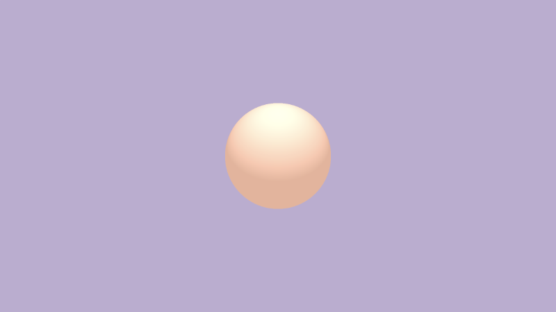
Let’s analyze the code to make sure we understand how this ray marching template works. At the beginning of the code, we are defining constants we learned about in Part 6 of this tutorial series.
1const int MAX_MARCHING_STEPS = 255;
2const float MIN_DIST = 0.0;
3const float MAX_DIST = 100.0;
4const float PRECISION = 0.001;
5const float EPSILON = 0.0005;
6const float PI = 3.14159265359;
7const vec3 COLOR_BACKGROUND = vec3(.741, .675, .82);
8const vec3 COLOR_AMBIENT = vec3(0.42, 0.20, 0.1);
We are defining the background color and ambient light color using variables, so we can quickly change how the 3D object will look under different colors.
Next, we are defining the rotate2d function for rotating an object along a 2D plane. This was discussed in Part 10. We’ll use it to move the camera around our 3D model with our mouse.
1mat2 rotate2d(float theta) {
2  float s = sin(theta), c = cos(theta);
3  return mat2(c, -s, s, c);
4}
The following functions are basic utility functions for creating a 3D scene. We learned about these in Part 6 when we first learned about ray marching. The sdSphere function is an SDF used to create a sphere. The scene function is used to render all the objects in our scene. You may often see this called the map function as you read other peoples’ code on Shadertoy.
 1float sdSphere(vec3 p, float r, vec3 offset)
 2{
 3  return length(p - offset) - r;
 4}
 5
 6float scene(vec3 p) {
 7  return sdSphere(p, 1., vec3(0));
 8}
 9
10float rayMarch(vec3 ro, vec3 rd) {
11  float depth = MIN_DIST;
12  float d; // distance ray has travelled
13
14  for (int i = 0; i < MAX_MARCHING_STEPS; i++) {
15    vec3 p = ro + depth * rd;
16    d = scene(p);
17    depth += d;
18    if (d < PRECISION || depth > MAX_DIST) break;
19  }
20
21  d = depth;
22
23  return d;
24}
25
26vec3 calcNormal(in vec3 p) {
27    vec2 e = vec2(1, -1) * EPSILON;
28    return normalize(
29      e.xyy * scene(p + e.xyy) +
30      e.yyx * scene(p + e.yyx) +
31      e.yxy * scene(p + e.yxy) +
32      e.xxx * scene(p + e.xxx));
33}
Next, we have the camera function that is used to define our camera model with a lookat point. This was discussed in Part 10. The lookat point camera model lets us point the camera at a target.
1mat3 camera(vec3 cameraPos, vec3 lookAtPoint) {
2	vec3 cd = normalize(lookAtPoint - cameraPos);
3	vec3 cr = normalize(cross(vec3(0, 1, 0), cd));
4	vec3 cu = normalize(cross(cd, cr));
5
6	return mat3(-cr, cu, -cd);
7}
Now, let’s analyze the mainImage function. We are setting up the UV coordinates so that the pixel coordinates will be between -0.5 and 0.5. We also account for the aspect ratio, which means the x-axis will have values that will go between different values, but still go between a negative value and positive value.
1vec2 uv = (fragCoord-.5*iResolution.xy)/iResolution.y;Since we’re using the mouse to rotate around the 3D object, we need to setup mouseUV coordinates. We’ll setup such that the coordinates go between zero and one when we click on the canvas.
1vec2 mouseUV = iMouse.xy/iResolution.xy;There’s an issue though. When we publish our shader on Shadertoy, and a user loads our shader for the first time, the coordinates will start at (0, 0) for the mouseUV coordinates. We can “trick” the shader by assigning it a new value when this happens.
1if (mouseUV == vec2(0.0)) mouseUV = vec2(0.5); // trick to center mouse on page loadNext, we declare a color variable, col, with an arbitrary starting value. Then, we setup the lookat point, lp, and the ray origin, ro. This was also discussed in Part 10. Our sphere currently has no offset in the scene function, so it’s located at (0, 0, 0). We should make the lookat point have the same value, but we can adjust it as needed.
1vec3 col = vec3(0);
2vec3 lp = vec3(0); // lookat point
3vec3 ro = vec3(0, 0, 3); // ray origin that represents camera position
We can use the mouse to rotate around the camera, but we have to be conscious of how far away the camera is from the 3D object. As we learned at the end of Part 10, we can use the rotate2d function to move the camera around and use cameraRadius to control how far away the camera is.
1float cameraRadius = 2.;
2ro.yz = ro.yz * cameraRadius * rotate2d(mix(-PI/2., PI/2., mouseUV.y));
3ro.xz = ro.xz * rotate2d(mix(-PI, PI, mouseUV.x)) + vec2(lp.x, lp.z);
4
5vec3 rd = camera(ro, lp) * normalize(vec3(uv, -1)); // ray direction
I hope that makes sense! There are alternative ways to implement cameras out there on Shadertoy. Each person sets it up slightly different. Choose whichever approach works best for you.
Combination 3D SDF Operations
Now that we understand the ray marching template I have provided, let’s learn about 3D SDF Operations! I covered 2D SDF operations in Part 5 of this tutorial series. 3D SDF operations are a bit similar. We will use utility functions to combine shapes together or subtract shapes from one another. These functions can be found on Inigo Quilez’s 3D SDFs page.
Define the utility functions near the top of your code and then use it inside the scene function.
Union: combine two shapes together or show multiple shapes on the screen. We should be familiar with a union operation by now. We’ve been using the min function to draw multiple shapes.
1float opUnion(float d1, float d2) {
2  return min(d1, d2);
3}
4
5float scene(vec3 p) {
6  float d1 = sdSphere(p, 1., vec3(0, -1, 0));
7  float d2 = sdSphere(p, 0.75, vec3(0, 0.5, 0));
8  return opUnion(d1, d2);
9}
Smooth Union: combine two shapes together and blend them at the edges using the parameter, k. A value of k equal to zero will result in a normal union operation.
 1float opSmoothUnion(float d1, float d2, float k) {
 2  float h = clamp( 0.5 + 0.5*(d2-d1)/k, 0.0, 1.0 );
 3  return mix( d2, d1, h ) - k*h*(1.0-h);
 4}
 5
 6float scene(vec3 p) {
 7  float d1 = sdSphere(p, 1., vec3(0, -1, 0));
 8  float d2 = sdSphere(p, 0.75, vec3(0, 0.5, 0));
 9  return opSmoothUnion(d1, d2, 0.2);
10}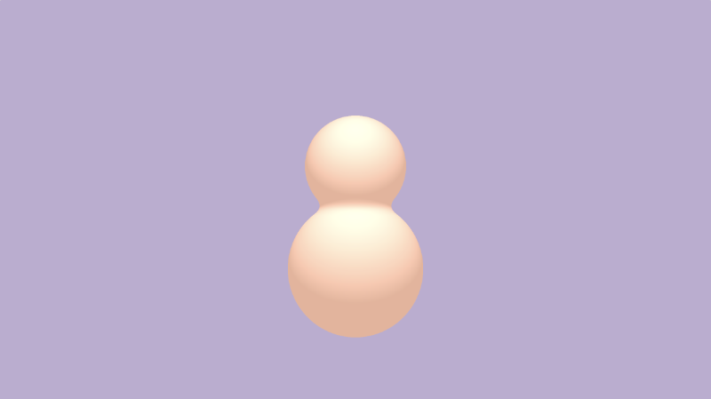
Intersection: take only the part where the two shapes intersect.
1float opIntersection(float d1, float d2) {
2  return max(d1,d2);
3}
4
5float scene(vec3 p) {
6  float d1 = sdSphere(p, 1., vec3(0, -1, 0));
7  float d2 = sdSphere(p, 0.75, vec3(0, 0.5, 0));
8  return opIntersection(d1, d2);
9}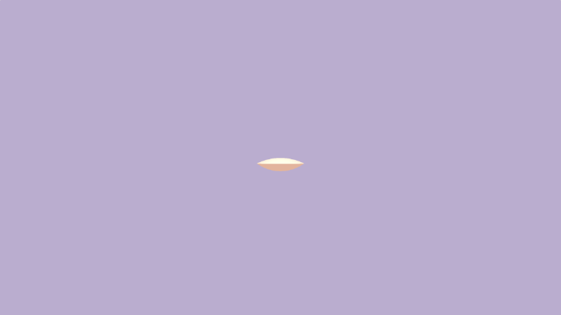
Smooth Intersection: combine two shapes together and blend them at the edges using the parameter, k. A value of k equal to zero will result in a normal intersection operation.
 1float opSmoothIntersection(float d1, float d2, float k) {
 2  float h = clamp( 0.5 - 0.5*(d2-d1)/k, 0.0, 1.0 );
 3  return mix( d2, d1, h ) + k*h*(1.0-h);
 4}
 5
 6float scene(vec3 p) {
 7  float d1 = sdSphere(p, 1., vec3(0, -1, 0));
 8  float d2 = sdSphere(p, 0.75, vec3(0, 0.5, 0));
 9  return opSmoothIntersection(d1, d2, 0.2);
10}
Subtraction: subtract d1 from d2.
1float opSubtraction(float d1, float d2 ) {
2  return max(-d1, d2);
3}
4
5float scene(vec3 p) {
6  float d1 = sdSphere(p, 1., vec3(0, -1, 0));
7  float d2 = sdSphere(p, 0.75, vec3(0, 0.5, 0));
8  return opSubtraction(d1, d2);
9}
Smooth Subtraction: subtract d1 from d2 smoothly around the edges using k.
 1float opSmoothSubtraction(float d1, float d2, float k) {
 2  float h = clamp( 0.5 - 0.5*(d2+d1)/k, 0.0, 1.0 );
 3  return mix( d2, -d1, h ) + k*h*(1.0-h);
 4}
 5
 6float scene(vec3 p) {
 7  float d1 = sdSphere(p, 1., vec3(0, -1, 0));
 8  float d2 = sdSphere(p, 0.75, vec3(0, 0.5, 0));
 9  return opSmoothSubtraction(d1, d2, 0.2);
10}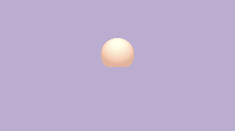
Subtraction 2: subtract d2 from d1.
1float opSubtraction2(float d1, float d2 ) {
2  return max(d1, -d2);
3}
4
5float scene(vec3 p) {
6  float d1 = sdSphere(p, 1., vec3(0, -1, 0));
7  float d2 = sdSphere(p, 0.75, vec3(0, 0.5, 0));
8  return opSubtraction2(d1, d2);
9}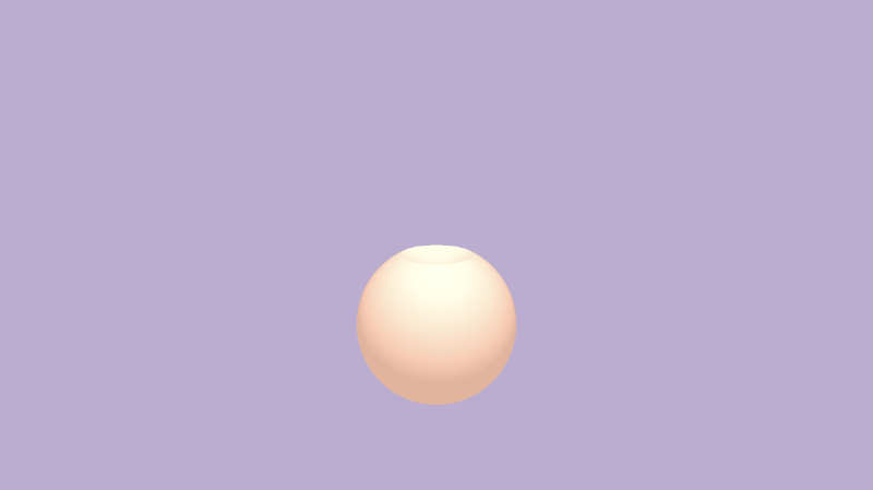
Smooth Subtraction 2: subtract d2 from d1 smoothly around the edges using k.
 1float opSmoothSubtraction2(float d1, float d2, float k) {
 2  float h = clamp( 0.5 - 0.5*(d2+d1)/k, 0.0, 1.0 );
 3  return mix( d1, -d2, h ) + k*h*(1.0-h);
 4}
 5
 6float scene(vec3 p) {
 7  float d1 = sdSphere(p, 1., vec3(0, -1, 0));
 8  float d2 = sdSphere(p, 0.75, vec3(0, 0.5, 0));
 9  return opSmoothSubtraction2(d1, d2, 0.2);
10}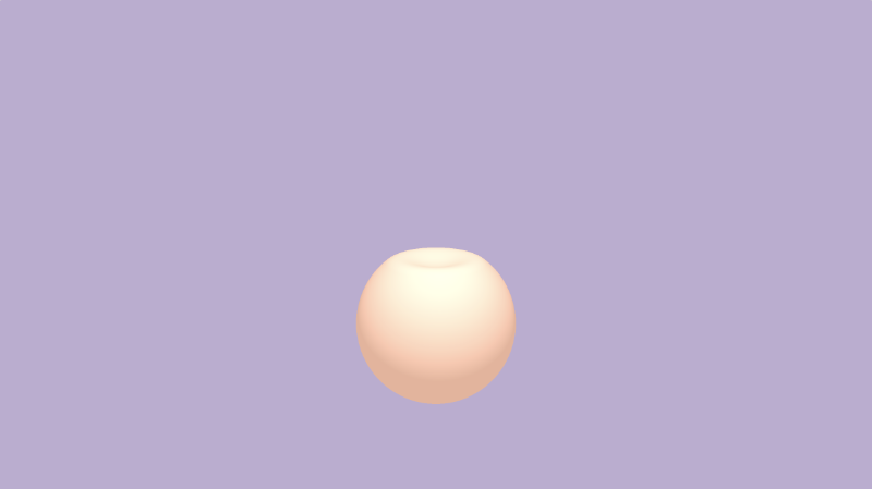
Positional 3D SDF Operations
Inigo Quilez’s 3D SDFs page describes a set of positional 3D SDF operations we can use to help save us some work when drawing 3D objects. Some of these operations help save on performance as well, since we don’t have to run the ray marching loop extra times.
We’ve learned in previous tutorials how to rotate shapes with a transformation matrix and translate 3D shapes with an offset. If you need to scale a shape, you can simply change the dimensions of the SDF.
If you’re drawing a symmetrical scene, then it may be useful to use the opSymX operation. This operation will create a duplicate 3D object along the x-axis using the SDF you provide. If we draw the sphere at an offset of vec3(1, 0, 0), then an equivalent sphere will be drawn at vec3(-1, 0, 0).
1float opSymX(vec3 p, float r, vec3 o)
2{
3  p.x = abs(p.x);
4  return sdSphere(p, r, o);
5}
6
7float scene(vec3 p) {
8  return opSymX(p, 1., vec3(1, 0, 0));
9}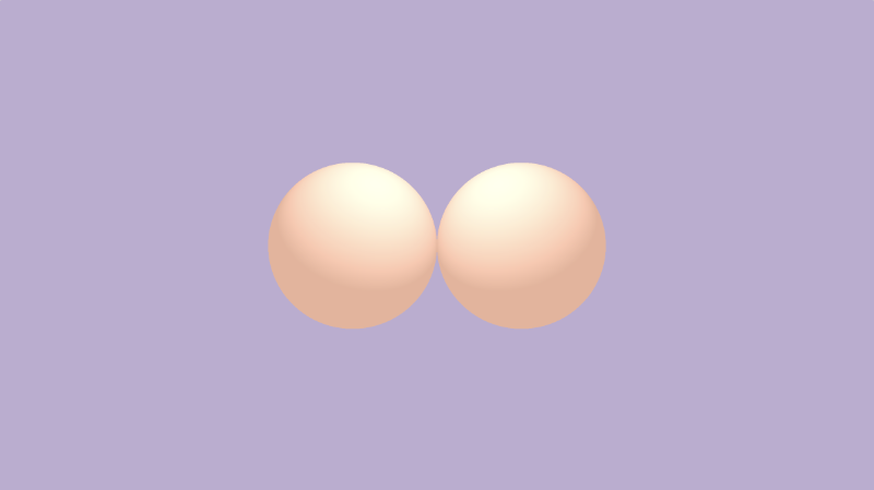
If you want to use symmetry along the y-axis or z-axis, you can replace p.x with p.y or p.z, respectively. Don’t forget to adjust the sphere offset as well.
If you want to draw spheres along two axes instead of just one, then you can use the opSymXZ operation. This will create a duplicate along the XZ plane, resulting in four spheres. If we draw a sphere with an offset of vec3(1, 0, 1), then a sphere will be drawn at vec3(1, 0, 1), vec3(-1, 0, 1), vec3(1, 0, -1), and vec3(-1, 0, -1).
1float opSymXZ(vec3 p, float r, vec3 o)
2{
3 p.xz = abs(p.xz);
4 return sdSphere(p, r, o);
5}
6
7float scene(vec3 p) {
8 return opSymXZ(p, 1., vec3(1, 0, 1));
9}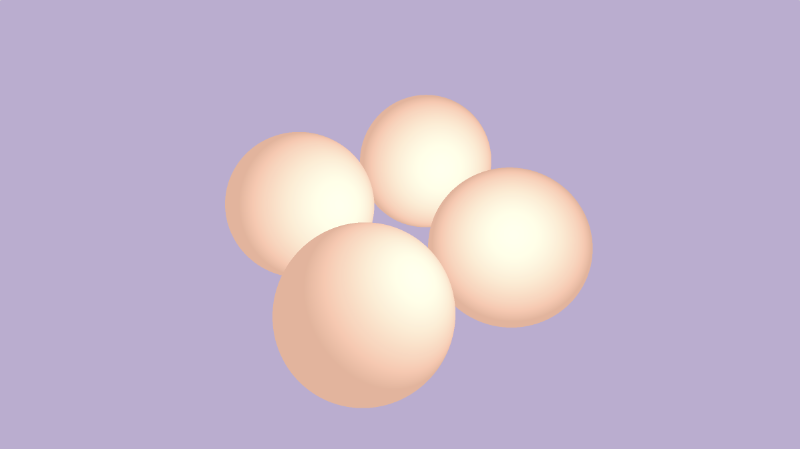
Sometimes, you want to create an infinite number of 3D objects across one or more axes. You can use the opRep operation to repeat spheres along the axes of your choice. The parameter, c, is a vector used to control the spacing between the 3D objects along each axis.
1float opRep(vec3 p, float r, vec3 o, vec3 c)
2{
3 vec3 q = mod(p+0.5*c,c)-0.5*c;
4 return sdSphere(q, r, o);
5}
6
7float scene(vec3 p) {
8 return opRep(p, 1., vec3(0), vec3(8));
9}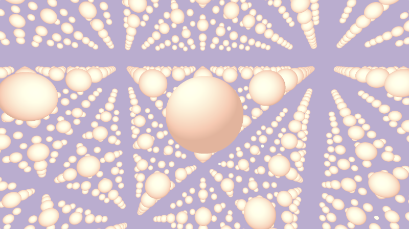
If you want to repeat the 3D objects only a certain number of times instead of an infinite amount, you can use the opRepLim operation. The parameter, c, is now a float value and still controls the spacing between each repeated 3D object. The parameter, l, is a vector that lets you control how many times the shape should be repeated along a given axis. For example, a value of vec3(1, 0, 1) would draw an extra sphere along the positive and negative x-axis and z-axis.
1float opRepLim(vec3 p, float r, vec3 o, float c, vec3 l)
2{
3 vec3 q = p-c*clamp(round(p/c),-l,l);
4 return sdSphere(q, r, o);
5}
6
7float scene(vec3 p) {
8 return opRepLim(p, 0.5, vec3(0), 2., vec3(1, 0, 1));
9}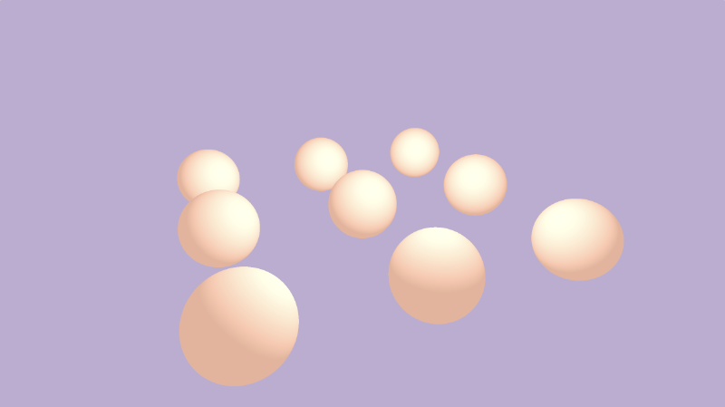
You can also perform deformations or distortions to an SDF by manipulating the value of p and adding it to the value returned from an SDF. Inside the opDisplace operation, you can create any type of mathematical operation you want to displace the value of p and then add that result to the original value you get back from an SDF.
1float opDisplace(vec3 p, float r, vec3 o)
2{
3 float d1 = sdSphere(p, r, o);
4 float d2 = sin(p.x)*sin(p.y)*sin(p.z) * cos(iTime);
5 return d1 + d2;
6}
7
8float scene(vec3 p) {
9 return opDisplace(p, 1., vec3(0));
10}
You can find the finished code, including an example of each 3D SDF operation, below.
1const int MAX_MARCHING_STEPS = 255;
2const float MIN_DIST = 0.0;
3const float MAX_DIST = 100.0;
4const float PRECISION = 0.001;
5const float EPSILON = 0.0005;
6const float PI = 3.14159265359;
7const vec3 COLOR_BACKGROUND = vec3(.741, .675, .82);
8const vec3 COLOR_AMBIENT = vec3(0.42, 0.20, 0.1);
9
10mat2 rotate2d(float theta) {
11 float s = sin(theta), c = cos(theta);
12 return mat2(c, -s, s, c);
13}
14
15float sdSphere(vec3 p, float r, vec3 offset)
16{
17 return length(p - offset) - r;
18}
19
20float opUnion(float d1, float d2) {
21 return min(d1, d2);
22}
23
24float opSmoothUnion(float d1, float d2, float k) {
25 float h = clamp( 0.5 + 0.5*(d2-d1)/k, 0.0, 1.0 );
26 return mix( d2, d1, h ) - k*h*(1.0-h);
27}
28
29float opIntersection(float d1, float d2) {
30 return max(d1, d2);
31}
32
33float opSmoothIntersection(float d1, float d2, float k) {
34 float h = clamp( 0.5 - 0.5*(d2-d1)/k, 0.0, 1.0 );
35 return mix( d2, d1, h ) + k*h*(1.0-h);
36}
37
38float opSubtraction(float d1, float d2) {
39 return max(-d1, d2);
40}
41
42float opSmoothSubtraction(float d1, float d2, float k) {
43 float h = clamp( 0.5 - 0.5*(d2+d1)/k, 0.0, 1.0 );
44 return mix( d2, -d1, h ) + k*h*(1.0-h);
45}
46
47float opSubtraction2(float d1, float d2) {
48 return max(d1, -d2);
49}
50
51float opSmoothSubtraction2(float d1, float d2, float k) {
52 float h = clamp( 0.5 - 0.5*(d2+d1)/k, 0.0, 1.0 );
53 return mix( d1, -d2, h ) + k*h*(1.0-h);
54}
55
56float opSymX(vec3 p, float r, vec3 o)
57{
58 p.x = abs(p.x);
59 return sdSphere(p, r, o);
60}
61
62float opSymXZ(vec3 p, float r, vec3 o)
63{
64 p.xz = abs(p.xz);
65 return sdSphere(p, r, o);
66}
67
68float opRep(vec3 p, float r, vec3 o, vec3 c)
69{
70 vec3 q = mod(p+0.5*c,c)-0.5*c;
71 return sdSphere(q, r, o);
72}
73
74float opRepLim(vec3 p, float r, vec3 o, float c, vec3 l)
75{
76 vec3 q = p-c*clamp(round(p/c),-l,l);
77 return sdSphere(q, r, o);
78}
79
80float opDisplace(vec3 p, float r, vec3 o)
81{
82 float d1 = sdSphere(p, r, o);
83 float d2 = sin(p.x)*sin(p.y)*sin(p.z) * cos(iTime);
84 return d1 + d2;
85}
86
87float scene(vec3 p) {
88 float d1 = sdSphere(p, 1., vec3(0, -1, 0));
89 float d2 = sdSphere(p, 0.75, vec3(0, 0.5, 0));
90 //return d1;
91 //return d2;
92 //return opUnion(d1, d2);
93 //return opSmoothUnion(d1, d2, 0.2);
94 //return opIntersection(d1, d2);
95 //return opSmoothIntersection(d1, d2, 0.2);
96 //return opSubtraction(d1, d2);
97 //return opSmoothSubtraction(d1, d2, 0.2);
98 //return opSubtraction2(d1, d2);
99 //return opSmoothSubtraction2(d1, d2, 0.2);
100 //return opSymX(p, 1., vec3(1, 0, 0));
101 //return opSymXZ(p, 1., vec3(1, 0, 1));
102 //return opRep(p, 1., vec3(0), vec3(8));
103 //return opRepLim(p, 0.5, vec3(0), 2., vec3(1, 0, 1));
104 return opDisplace(p, 1., vec3(0));
105}
106
107float rayMarch(vec3 ro, vec3 rd) {
108 float depth = MIN_DIST;
109 float d; // distance ray has travelled
110
111 for (int i = 0; i < MAX_MARCHING_STEPS; i++) {
112 vec3 p = ro + depth * rd;
113 d = scene(p);
114 depth += d;
115 if (d < PRECISION || depth > MAX_DIST) break;
116 }
117
118 d = depth;
119
120 return d;
121}
122
123vec3 calcNormal(in vec3 p) {
124 vec2 e = vec2(1, -1) * EPSILON;
125 return normalize(
126 e.xyy * scene(p + e.xyy) +
127 e.yyx * scene(p + e.yyx) +
128 e.yxy * scene(p + e.yxy) +
129 e.xxx * scene(p + e.xxx));
130}
131
132mat3 camera(vec3 cameraPos, vec3 lookAtPoint) {
133 vec3 cd = normalize(lookAtPoint - cameraPos);
134 vec3 cr = normalize(cross(vec3(0, 1, 0), cd));
135 vec3 cu = normalize(cross(cd, cr));
136
137 return mat3(-cr, cu, -cd);
138}
139
140void mainImage( out vec4 fragColor, in vec2 fragCoord )
141{
142 vec2 uv = (fragCoord-.5*iResolution.xy)/iResolution.y;
143 vec2 mouseUV = iMouse.xy/iResolution.xy;
144
145 if (mouseUV == vec2(0.0)) mouseUV = vec2(0.5); // trick to center mouse on page load
146
147 vec3 col = vec3(0);
148 vec3 lp = vec3(0);
149 vec3 ro = vec3(0, 0, 3); // ray origin that represents camera position
150
151 float cameraRadius = 2.;
152 ro.yz = ro.yz * cameraRadius * rotate2d(mix(-PI/2., PI/2., mouseUV.y));
153 ro.xz = ro.xz * rotate2d(mix(-PI, PI, mouseUV.x)) + vec2(lp.x, lp.z);
154
155 vec3 rd = camera(ro, lp) * normalize(vec3(uv, -1)); // ray direction
156
157 float d = rayMarch(ro, rd); // signed distance value to closest object
158
159 if (d > MAX_DIST) {
160 col = COLOR_BACKGROUND; // ray didn't hit anything
161 } else {
162 vec3 p = ro + rd * d; // point discovered from ray marching
163 vec3 normal = calcNormal(p); // surface normal
164
165 vec3 lightPosition = vec3(0, 2, 2);
166 vec3 lightDirection = normalize(lightPosition - p) * .65; // The 0.65 is used to decrease the light intensity a bit
167
168 float dif = clamp(dot(normal, lightDirection), 0., 1.) * 0.5 + 0.5; // diffuse reflection mapped to values between 0.5 and 1.0
169
170 col = vec3(dif) + COLOR_AMBIENT;
171 }
172
173 fragColor = vec4(col, 1.0);
174}Conclusion
In this tutorial, we learned how to use “combination” SDF operations such as unions, intersections, and subtractions. We also learned how to use “positional” SDF operations to help draw duplicate objects to the scene along different axes. In the resources, I have included a link to the ray marching template I created at the beginning of this tutorial and a link to my shader that includes examples of each 3D SDF operation.
There are many other 3D SDF operations that I didn’t discuss in this article. Please check out the other resources below to see examples created by Inigo Quilez on how to use them.
Resources
- Ray Marching Template
- 3D SDF Operations
- Combination
- Elongation
- Rounding
- Onion
- Metric
- Repetition
- Extrusion2D
- Revolution2D
- Ray Marching Primitives
- Ray Marching Primitives Commented
Tutorial Part 15 - Channels, Textures, and Buffers
转自:https://inspirnathan.com/posts/62-shadertoy-tutorial-part-15
Greetings, friends! Welcome to Part 15 of my Shadertoy tutorial series! In this tutorial, I’ll discuss how to use channels and buffers in Shadertoy, so we can use textures and create multi-pass shaders.
Channels
Shadertoy uses a concept known as channels to access different types of data. At the bottom of the Shadertoy user interface, you will see four black boxes: iChannel0, iChannel1, iChannel2, and iChannel3.
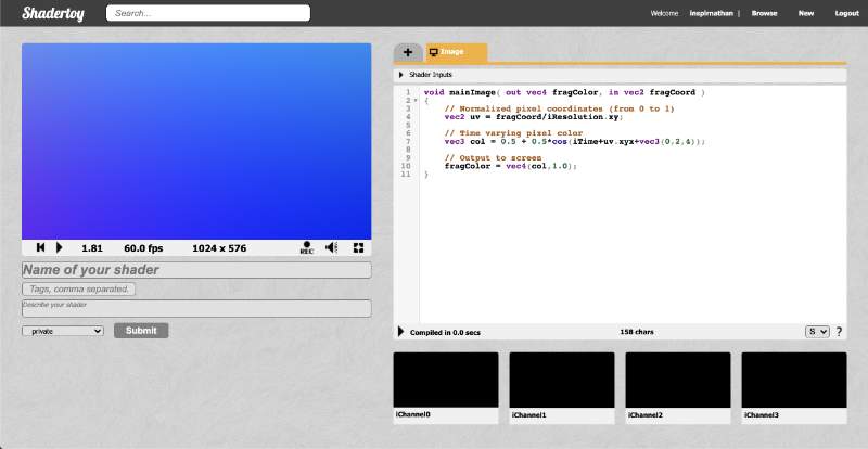
If you click any of the channels, a popup will appear. You can select from a variety of interactive elements, textures, cubemaps, volumes, videos, and music.
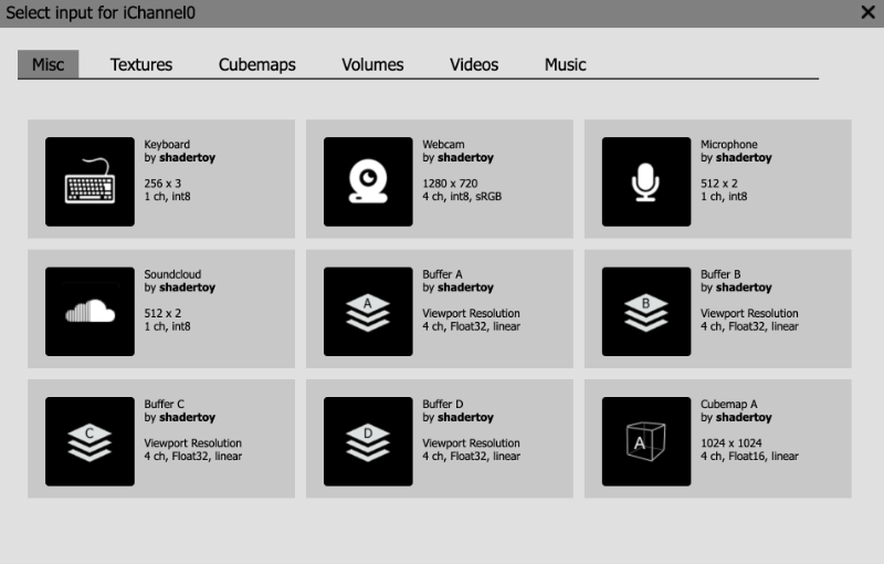
In the “Misc” tab, you can select from interactive elements such as a keyboard, a webcam, a microphone, or even play music from SoundCloud. The buffers, Buffer A, Buffer B, Buffer C, and Buffer D, let you create “multi-pass” shaders. Think of them as an extra shader you can add to your shader pipeline. The “Cubemap A” input is a special type of shader program that lets you create your own cubemap. You can then pass that cubemap to a buffer or to your main “Image” program. We’ll talk about cubemaps in the next tutorial.
The next tab is the “Textures” tab. You will find three pages worth of 2D textures to choose from. Think of 2D textures as images we can pull pixel values from. As of the time of this writing, you can only use textures Shadertoy provides for you and can’t import images from outside of Shadertoy. However, there are ways to circumvent this locally using details found in this shader.
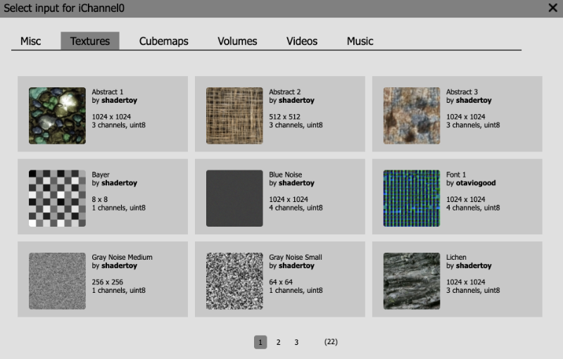
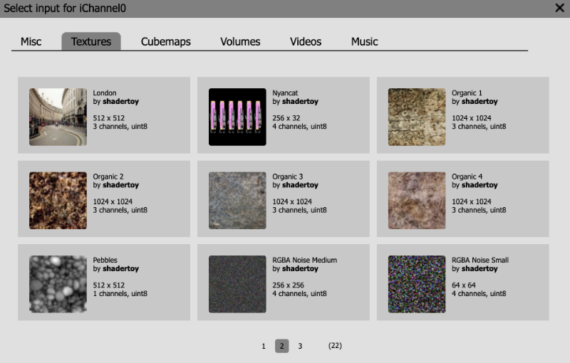
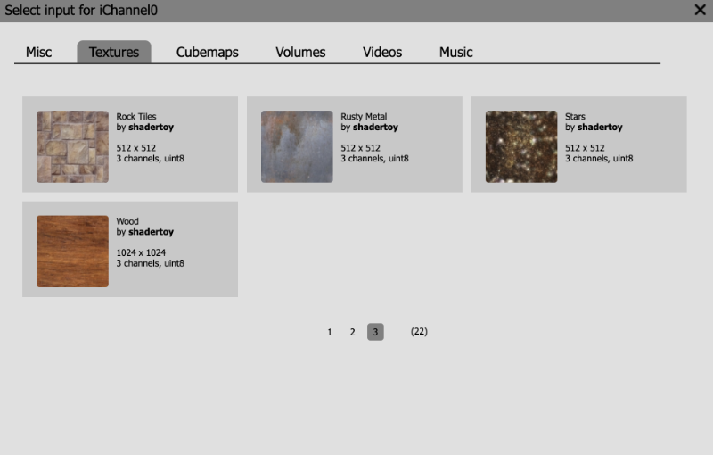
The “Cubemaps” tab contains a selection of cubemaps you can choose from. We will talk about them more in the next tutorial. Cubemaps are commonly used in game engines such as Unity for rendering a 3D world around you.
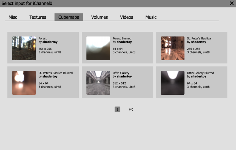
The “Volumes” tab contains 3D textures. Typical 2D textures use UV coordinates to access data along the x-axis (U value) and y-axis (V value). In 3D textures, you use UVW coordinates where the W value is for the z-axis. You can think of 3D textures as a cube where each pixel on the cube represents data we can pull from. It’s like pulling data from a three-dimensional array.
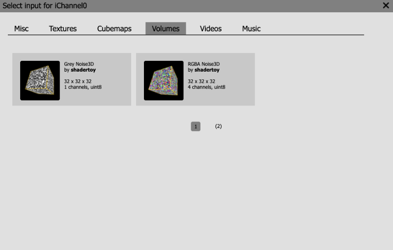
The “Videos” tab contains 2D textures (or images) that change with time. That is, they play videos in the Shadertoy canvas. People use videos on Shadertoy to experiment with postprocessing effects or image effects that rely on data from the previous frame. The “Britney Spears” and “Claude Van Damme” videos are great for testing out green screen effects (aka Chroma key compositing).
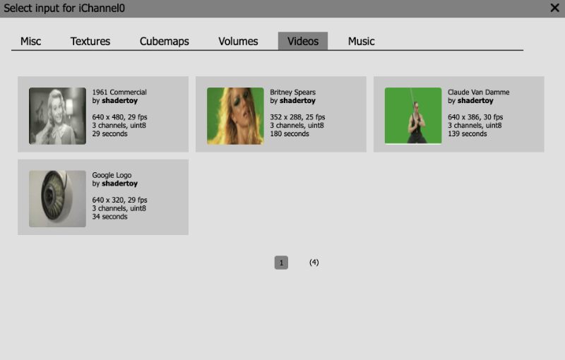
Finally, the “Music” tab lets you play from a range of songs that Shadertoy provides for you. The music will play automatically when a user visits your Shader if you have chosen a song from this tab in one of your channels.
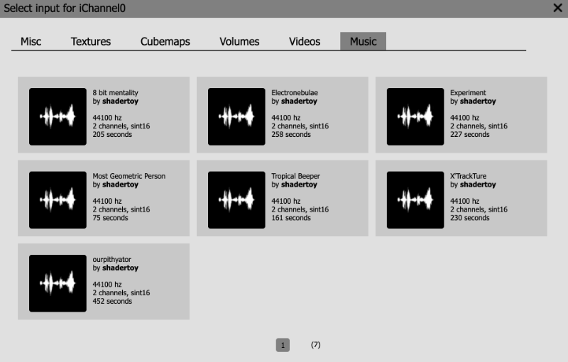
Using Textures
Using textures is very simple in Shadertoy. Open a new shader and replace the code with the following contents:
1void mainImage( out vec4 fragColor, in vec2 fragCoord )
2{
3 vec2 uv = fragCoord/iResolution.xy; // Normalized pixel coordinates (from 0 to 1)
4
5 vec4 col = texture(iChannel0, uv);
6
7 fragColor = vec4(col); // Output to screen
8}Then, click on the iChannel0 box. When the popup appears, go to the “Textures” tab. We will be choosing the “Abstract 1” texture, but let’s inspect some details displayed in the popup menu.
It says this texture has a resolution of 1024x1024 pixels, which implies this image is best viewed in a square-like or proportional canvas. It also has 3 channels (red, green, blue) which are each of type uint8, an unsigned integer of 8 bits.
Go ahead and click on “Abstract 1” to load this texture into iChannel0. Then, run your shader program. You should see the texture appear in the Shadertoy canvas.
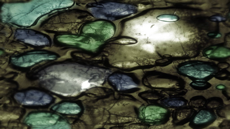
Let’s analyze the code in our shader program.
1void mainImage( out vec4 fragColor, in vec2 fragCoord )
2{
3 vec2 uv = fragCoord/iResolution.xy; // Normalized pixel coordinates (from 0 to 1)
4
5 vec4 col = texture(iChannel0, uv);
6
7 fragColor = vec4(col); // Output to screen
8}The UV coordinates go between zero and one across the x-axis and y-axis. Remember, the point (0, 0) starts at the bottom-left corner of the canvas. The texture function retrieves what are known as “texels” from a texture using iChannel0 and the uv coordinates.
A texel is value at a particular coordinate on the texture. For 2D textures such as images, a texel is a pixel value. We sample 2D textures assuming the UV coordinates go between zero and one on the image. We can then “UV map” the texture onto our entire Shadertoy canvas.
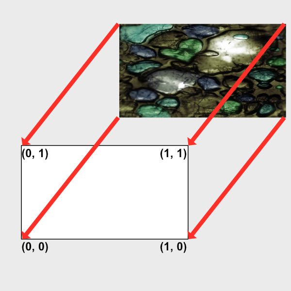
For 3D textures, you can think of a texel as a pixel value at a 3D coordinate. You typically won’t see 3D textures used that often unless you’re dealing with noise generation or volumetric ray marching.
You may be curious on what kind of type iChannel0 is when we pass it as a parameter to the texture function. Shadertoy takes care of setting up a sampler for you. A sampler is a way to bind texture units to a shader. The type of sampler will change depending on what kind of resource you load into one of the four channels (iChannel0, iChannel1, iChannel2, iChannel3).
In our case, we’re loading a 2D texture into iChannel0. Therefore, iChannel0 will have the type, sampler2D. You can see what other sampler types are available on the OpenGL wiki page.
Suppose you wanted to make a function that let you pass in one of the channels. You can do this through the following code:
1vec3 get2DTexture( sampler2D sam, vec2 uv ) {
2 return texture(sam, uv).rgb;
3}
4
5void mainImage( out vec4 fragColor, in vec2 fragCoord )
6{
7 vec2 uv = fragCoord/iResolution.xy; // Normalized pixel coordinates (from 0 to 1)
8
9 vec3 col = vec3(0.);
10
11 col = get2DTexture(iChannel0, uv);
12 col += get2DTexture(iChannel1, uv);
13
14 fragColor = vec4(col,1.0); // Output to screen
15}If you click on the iChannel1 box, select the “Abstract 3” texture, and run your code, you should see two images blended together.
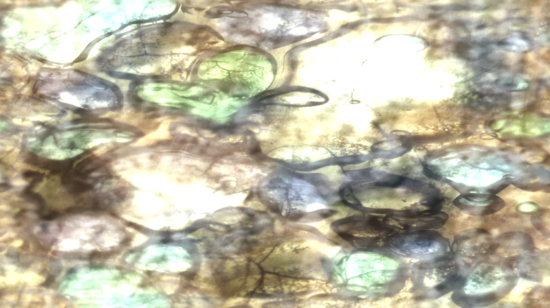
The get2DTexture function we created accepts a sampler2D type as its first parameter. When you use a 2D texture in a channel, Shadertoy automatically returns a sampler2D type of data for you.
If you want to play a video in the Shadertoy canvas, you can follow the same steps as for the 2D texture. Just choose a video inside iChannel0, and you should see the video start to play automatically.
Channel Settings
Alright, let’s now look into some channel settings we can change. First, paste the following code into your shader:
1void mainImage( out vec4 fragColor, in vec2 fragCoord )
2{
3 vec2 uv = fragCoord/iResolution.xy; // Normalized pixel coordinates (from 0 to 1)
4
5 vec4 col = texture(iChannel0, uv);
6
7 fragColor = vec4(col); // Output to screen
8}Then, we’re going to use a new texture. Click on the iChannel0 box, go to the “Textures” tab, go to page 2, and you should see a “Nyancat” texture.
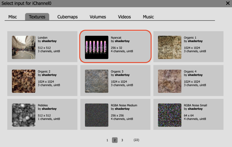
The “Nyancat” texture is a 256x32 image with 4 channels (red, green, blue, and alpha). Click on this texture, so it shows up in iChannel0.
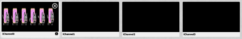
When you run the code, you should see Nyan Cats appear, but they appear blurry.
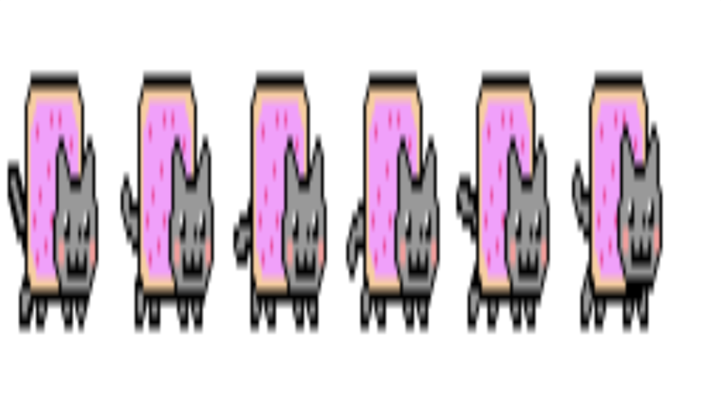
To fix this, we need to adjust the channel settings by clicking the little gear icon on the bottom right corner of the channel box.
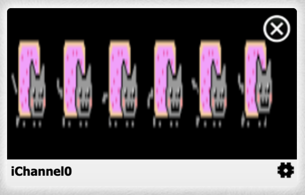
This will open up a menu with three settings: Filter, Wrap, and VFlip.
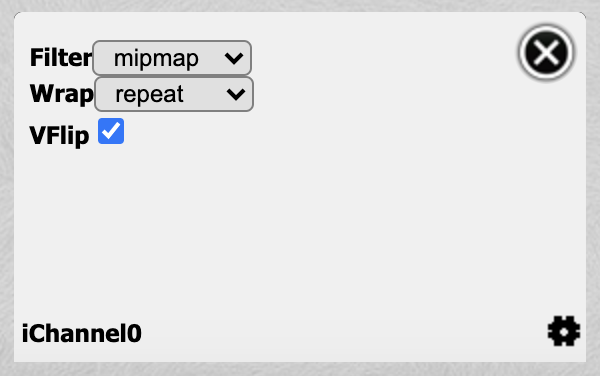
The Filter option lets you change the type of algorithm used to filter the texture. The dimensions of the texture and the Shadertoy canvas won’t always match, so a filter is used to sample the texture. By default, the Filter option is set to “mipmap.” Click on the dropdown menu and choose “nearest” to use “nearest-neighbor interpolation.” This type of filter is useful for when you have textures or images that are pixelated, and you want to keep that pixelated look.
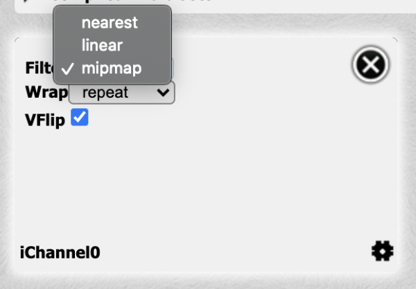
When you change the filter to “nearest,” you should see the Nyan Cats look super clear and crisp.

The Nyan Cats look a bit squished though. Let’s fix that by scaling the x-axis by 0.25.
1void mainImage( out vec4 fragColor, in vec2 fragCoord )
2{
3 vec2 uv = fragCoord/iResolution.xy; // Normalized pixel coordinates (from 0 to 1)
4
5 uv.x *= 0.25;
6
7 vec4 col = texture(iChannel0, uv);
8
9 fragColor = vec4(col); // Output to screen
10}When you run the code, the Nyan Cats won’t look squished anymore.
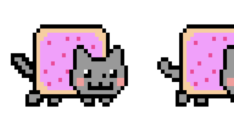
You can use the VFlip option to flip the texture upside down or vertically. Uncheck the checkbox next to VFlip in the channel settings to see the Nyan Cats flip upside down.
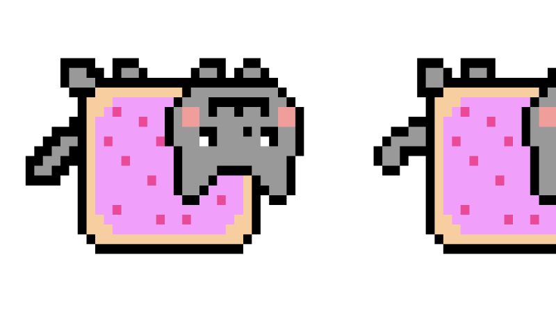
Go back and check the VFlip option to return the Nyan Cats to normal. You can make the Nyan Cats move by subtracting an offset from uv.x and using iTime to animate the scene.
1void mainImage( out vec4 fragColor, in vec2 fragCoord )
2{
3 vec2 uv = fragCoord/iResolution.xy; // Normalized pixel coordinates (from 0 to 1)
4
5 uv.x *= 0.25;
6
7 uv.x -= iTime * 0.05;
8
9 vec4 col = texture(iChannel0, uv);
10
11 fragColor = vec4(col); // Output to screen
12}
By default, the Wrap mode is set to “repeat.” This means that when the UV coordinates are outside the boundary of zero and one, it’ll start sampling from the texture and repeat between zero and one. Since we’re making uv.x smaller and smaller, we definitely go outside the boundary of zero, but the sampler is smart enough to figure out how to adapt.
If you don’t want this repeating behavior, you can set the Wrap mode to “clamp” instead.
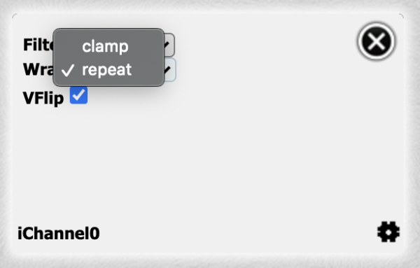
If you reset the time back to zero, then you’ll see that after the UV coordinates go outside the boundary of zero or one, we don’t see the Nyan Cats anymore.
Since the “Nyancat” texture provides four channels and therefore an alpha channel, we can easily swap out the background. Make sure the timer is set back to zero and run the following code:
1void mainImage( out vec4 fragColor, in vec2 fragCoord )
2{
3 vec2 uv = fragCoord/iResolution.xy; // Normalized pixel coordinates (from 0 to 1)
4
5 vec4 col = vec4(0.75);
6
7 uv.x *= 0.25;
8 uv.x -= iTime * 0.05;
9
10 vec4 texCol = texture(iChannel0, uv);
11
12 col = mix(col, texCol, texCol.a);
13
14 fragColor = vec4(col); // Output to screen
15}The “Nyancat” texture has an alpha value of zero everwhere except for where the Nyan Cats are. This lets us set a background color behind them.
Keep in mind that most textures are only three channels. Some textures only have one channel such as the “Bayer” texture. This means that the red channel will contain data, but the other three channels will not, which is why you will likely see red when you use it. Some textures are used for creating noise or displacing shapes a particular way. You can even use textures as height maps to shape the height of terrains based on the color values stored inside the texture. Textures serve a variety of purposes.
Buffers
Shadertoy provides the support of buffers. You can run completely different shaders in each buffer. Each shader will have its own final fragColor that can be passed to another buffer or the main “Image” shader we’ve been working in.
There are four buffers: Buffer A, Buffer B, Buffer C, and Buffer D. Each buffer can hold its own four channels. To access a buffer, we use one of the four channels. Let’s practice with buffers to see how to use them.
Above your code, near the top of the Shadertoy user interface, you should see a tab labelled “Image.” The “Image” tab represents the main shader we’ve been using in the previous tutorials. To add a buffer, simply click on the plus sign (+) to the left of the Image tab.

From there, you’ll see a dropdown of items to choose from: Common, Sound, Buffer A, Buffer B, Buffer C, Buffer D, Cubemap A.
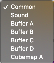
The Common option is used to share code between the “Image” shader, all buffers, and other shaders including Sound and Cubemap A. The Sound options lets you create a shader that generates sound. The Cubemap A option lets you generate your own cubemap. For this tutorial, I’ll go over the buffers, which are normal shaders that return a color of type vec4 (red, green, blue, alpha).
Go ahead and select Buffer A. You should see default code provided for you.
1void mainImage( out vec4 fragColor, in vec2 fragCoord )
2{
3 fragColor = vec4(0.0,0.0,1.0,1.0);
4}Looks like this code simply returns the color, blue, for each pixel. Next, let’s go back to the “Image” tab. Click on iChannel0, go to the “Misc” tab, and select Buffer A. You should now be using Buffer A for iChannel0. Inside the “Image” shader, paste the following code.
1void mainImage( out vec4 fragColor, in vec2 fragCoord )
2{
3 vec2 uv = fragCoord/iResolution.xy;
4
5 vec3 col = texture(iChannel0, uv).rgb;
6
7 col += vec3(1, 0, 0);
8
9 // Output to screen
10 fragColor = vec4(col, 1.0);
11}When you run the code, you should see the entire canvas turn purple. This is because we’re taking the color values from Buffer A, passing it into the Image shader, adding red to the blue color we got from Buffer A, and outputting the result to the screen.
Essentially, buffers give you more space to work with. You can create an entire shader in Buffer A, pass the result to another buffer to do more processing on it, and then pass the result to the Image shader to output the final result. Think of it as a pipeline where you keep passing the output of one shader to the next. This is why shaders that leverage buffers or additional shaders are often called multi-pass shaders.
Using the Keyboard
You may have seen shaders on Shadertoy that let users control the scene with a keyboard. I have written a shader that demonstrates how to move objects using a keyboard and uses a buffer to store the results of each key press. If you go to this shader, you should see a multi-pass shader with a buffer, Buffer A, and the main “Image” shader.
Inside Buffer A, you should see the following code:
1// Numbers are based on JavaScript key codes: https://keycode.info/
2const int KEY_LEFT = 37;
3const int KEY_UP = 38;
4const int KEY_RIGHT = 39;
5const int KEY_DOWN = 40;
6
7vec2 handleKeyboard(vec2 offset) {
8 float velocity = 1. / 100.; // This will cause offset to change by 0.01 each time an arrow key is pressed
9
10 // texelFetch(iChannel1, ivec2(KEY, 0), 0).x will return a value of one if key is pressed, zero if not pressed
11 vec2 left = texelFetch(iChannel1, ivec2(KEY_LEFT, 0), 0).x * vec2(-1, 0);
12 vec2 up = texelFetch(iChannel1, ivec2(KEY_UP,0), 0).x * vec2(0, 1);
13 vec2 right = texelFetch(iChannel1, ivec2(KEY_RIGHT, 0), 0).x * vec2(1, 0);
14 vec2 down = texelFetch(iChannel1, ivec2(KEY_DOWN, 0), 0).x * vec2(0, -1);
15
16 offset += (left + up + right + down) * velocity;
17
18 return offset;
19}
20
21void mainImage( out vec4 fragColor, in vec2 fragCoord )
22{
23 // Return the offset value from the last frame (zero if it's first frame)
24 vec2 offset = texelFetch( iChannel0, ivec2(0, 0), 0).xy;
25
26 // Pass in the offset of the last frame and return a new offset based on keyboard input
27 offset = handleKeyboard(offset);
28
29 // Store offset in the XY values of every pixel value and pass this data to the "Image" shader and the next frame of Buffer A
30 fragColor = vec4(offset, 0, 0);
31}Inside the “Image” shader, you should see the following code:
1float sdfCircle(vec2 uv, float r, vec2 offset) {
2 float x = uv.x - offset.x;
3 float y = uv.y - offset.y;
4
5 float d = length(vec2(x, y)) - r;
6
7 return step(0., -d);
8}
9
10vec3 drawScene(vec2 uv) {
11 vec3 col = vec3(0);
12
13 // Fetch the offset from the XY part of the pixel values returned by Buffer A
14 vec2 offset = texelFetch( iChannel0, ivec2(0,0), 0 ).xy;
15
16 float blueCircle = sdfCircle(uv, 0.1, offset);
17
18 col = mix(col, vec3(0, 0, 1), blueCircle);
19
20 return col;
21}
22
23void mainImage( out vec4 fragColor, in vec2 fragCoord )
24{
25 vec2 uv = fragCoord/iResolution.xy; // <0, 1>
26 uv -= 0.5; // <-0.5,0.5>
27 uv.x *= iResolution.x/iResolution.y; // fix aspect ratio
28
29 vec3 col = drawScene(uv);
30
31 // Output to screen
32 fragColor = vec4(col,1.0);
33}My multi-pass shader draws a circle to the canvas and lets you move it around using the keyboard. What’s actually happening is that we’re getting a value of one or zero from a key press and using that value to control the circle’s offset value.
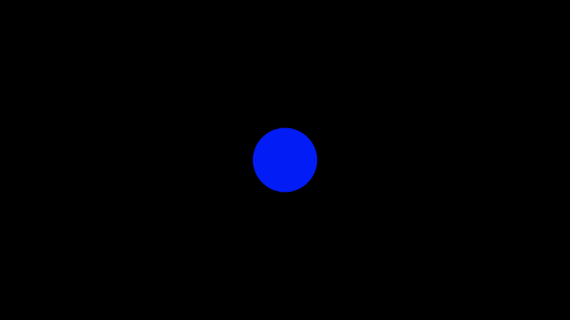
If you look inside Buffer A, you’ll notice that I’m using Buffer A in iChannel0 from within Buffer A. How is that possible? When you use Buffer A within the Buffer A shader, you will get access to the fragColor value from the last frame that was run.
There’s no recursion going on. You can’t use recursion in GLSL as far as I’m aware of. Therefore, everything must be coded in an iterative approach. However, that doesn’t stop us from using buffers on a frame by frame basis.
The texelFetch function performs a lookup of a single texel value within a texture. A keyboard isn’t a texture though, so how does that work? Shadertoy essentially glued things together in a way that lets us access the browser’s keyboard events from within a shader as if it were a texture. We can access key presses by using texelFetch to check if a key was pressed.
We get back a zero or one depending on whether a key isn’t pressed or is pressed, respectively. We can then multiply this value by a velocity to adjust the circle’s offset. The offset value will be passed to the next frame of Buffer A. Then, it’ll get passed to the “Image” shader.
If the scene is running at 60 frames per second (fps), then that means one frame is drawn every 1/60 of a second. During one pass of our multi-pass shader, we’ll pull from the last frame’s Buffer A value, pass that into the current frame’s Buffer A shader, pass that result to the “Image” shader, and then draw the pixel to the canvas. This cycle will repeat every frame or 60 times a second.
Other interactive elements such as our computer’s microphone can be accessed like textures as well. Please read the resources below to see examples created by Inigo Quilez on how to use various interactive elements in Shadertoy.
Conclusion
Textures are a very important concept in computer graphics and game development. GLSL and other shader languages provide functions for accessing texture data. Shadertoy takes care of a lot of the hard work for you, so you can quickly access textures or interactive elements via channels. You can use textures to store color values but then use those colors to represent different types of data such as height, displacement, depth, or whatever else you can think of.
Please see the resources below to learn how to use various interactive elements in Shadertoy.
Resources
- Khronos: Data Type (GLSL)
- Khronos: texture
- Khronos: texelFetch
- Khronos: Sampler (GLSL)
- 2D Movement with Keyboard
- Input - Keyboard
- Input - Microphone
- Input - Mouse
- Input - Sound
- Input - SoundCloud
- Input - Time
- Input - TimeDelta
- Input - 3D Texture
- Example - mainCubemap
- Cheap Cubemap
Tutorial Part 16 - Cubemaps and Reflections
转自:https://inspirnathan.com/posts/63-shadertoy-tutorial-part-16
Greetings, friends! Welcome to Part 16 of my Shadertoy tutorial series! In this tutorial, I’ll discuss how to use cubemaps in Shadertoy, so we can use draw 3D backgrounds and make more realistic reflections on any 3D object!
Cubemaps
Cubemaps are a special type of texture that can be thought of containing six individual 2D textures that each form a face of a cube. You may have used cubemaps in game engines such as Unity and Unreal Engine. In Shadertoy, cubemaps let you create a dynamic 3D background that changes depending on where the camera is facing. Each pixel of the Shadertoy canvas will be determined by the ray direction.
The website, Learn OpenGL, provides a great image to visualize how cubemaps work.
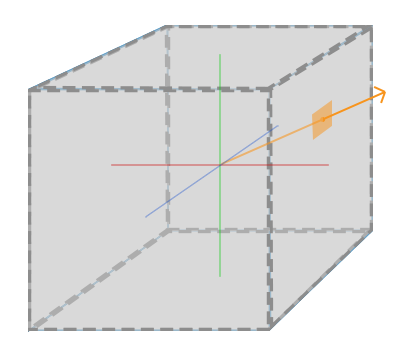
Cubemap by Learn OpenGL
We pretend the camera is in the center of the cube and points toward one or more faces of the cube. In the image above, the ray direction determines which part of the cubemap to sample from.
Let’s practice this in Shadertoy. Create a new shader and click on the iChannel0 box. Click on the “Cubemaps” tab and select the “Uffizi Gallery” cubemap.
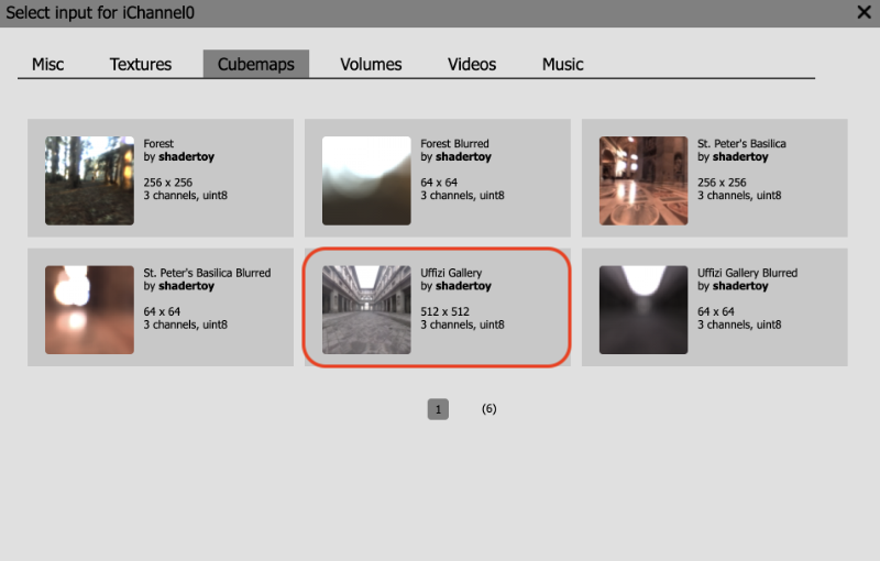
Then, replace all the code with the following:
1const float PI = 3.14159265359;
2
3mat2 rotate2d(float theta) {
4 float s = sin(theta), c = cos(theta);
5 return mat2(c, -s, s, c);
6}
7
8mat3 camera(vec3 cameraPos, vec3 lookAtPoint) {
9 vec3 cd = normalize(lookAtPoint - cameraPos);
10 vec3 cr = normalize(cross(vec3(0, 1, 0), cd));
11 vec3 cu = normalize(cross(cd, cr));
12
13 return mat3(-cr, cu, -cd);
14}
15
16void mainImage( out vec4 fragColor, in vec2 fragCoord )
17{
18 vec2 uv = (fragCoord-.5*iResolution.xy)/iResolution.y;
19 vec2 mouseUV = iMouse.xy/iResolution.xy;
20 if (mouseUV == vec2(0.0)) mouseUV = vec2(0.5); // trick to center mouse on page load
21
22 vec3 lp = vec3(0);
23 vec3 ro = vec3(0, 0, 3);
24 ro.yz *= rotate2d(mix(-PI/2., PI/2., mouseUV.y));
25 ro.xz *= rotate2d(mix(-PI, PI, mouseUV.x));
26
27 vec3 rd = camera(ro, lp) * normalize(vec3(uv, -1));
28
29 vec3 col = texture(iChannel0, rd).rgb;
30
31 fragColor = vec4(col, 1.0);
32}Does this code look familiar? I took part of the code we used at the beginning of Part 14 of my Shadertoy tutorial series for this tutorial. We use the lookat camera model to adjust the ray direction, rd.
The color of each pixel, col, will be equal to a color value sampled from the cubemap stored in iChannel0. We learned how to access textures in the previous tutorial. However, accessing values from a cubemap requires us to pass in the ray direction, rd, instead of uv coordinates like what we did for 2D textures.
1vec3 col = texture(iChannel0, rd).rgb;You can use the mouse to look around the cubemap because we’re using the iMouse global variable to control the ray origin, ro, which is the position of the camera. The camera function changes based on ro and lp, so the ray direction is changing as we move the mouse around. Looks like the background is a dynamic 3D scene now!
Reflections with Cubemap
Using cubemaps, we can make objects look reflective. Let’s add a sphere to the scene using ray marching.
Replace your code with the following:
1const int MAX_MARCHING_STEPS = 255;
2const float MIN_DIST = 0.0;
3const float MAX_DIST = 100.0;
4const float PRECISION = 0.001;
5const float EPSILON = 0.0005;
6const float PI = 3.14159265359;
7
8mat2 rotate2d(float theta) {
9 float s = sin(theta), c = cos(theta);
10 return mat2(c, -s, s, c);
11}
12
13float sdSphere(vec3 p, float r )
14{
15 return length(p) - r;
16}
17
18float sdScene(vec3 p) {
19 return sdSphere(p, 1.);
20}
21
22float rayMarch(vec3 ro, vec3 rd) {
23 float depth = MIN_DIST;
24
25 for (int i = 0; i < MAX_MARCHING_STEPS; i++) {
26 vec3 p = ro + depth * rd;
27 float d = sdScene(p);
28 depth += d;
29 if (d < PRECISION || depth > MAX_DIST) break;
30 }
31
32 return depth;
33}
34
35vec3 calcNormal(vec3 p) {
36 vec2 e = vec2(1.0, -1.0) * EPSILON;
37 float r = 1.;
38 return normalize(
39 e.xyy * sdScene(p + e.xyy) +
40 e.yyx * sdScene(p + e.yyx) +
41 e.yxy * sdScene(p + e.yxy) +
42 e.xxx * sdScene(p + e.xxx));
43}
44
45mat3 camera(vec3 cameraPos, vec3 lookAtPoint) {
46 vec3 cd = normalize(lookAtPoint - cameraPos);
47 vec3 cr = normalize(cross(vec3(0, 1, 0), cd));
48 vec3 cu = normalize(cross(cd, cr));
49
50 return mat3(-cr, cu, -cd);
51}
52
53vec3 phong(vec3 lightDir, float lightIntensity, vec3 rd, vec3 normal) {
54 vec3 cubemapReflectionColor = texture(iChannel0, reflect(rd, normal)).rgb;
55
56 vec3 K_a = 1.5 * vec3(0.0,0.5,0.8) * cubemapReflectionColor; // Reflection
57 vec3 K_d = vec3(1);
58 vec3 K_s = vec3(1);
59 float alpha = 50.;
60
61 float diffuse = clamp(dot(lightDir, normal), 0., 1.);
62 float specular = pow(clamp(dot(reflect(lightDir, normal), -rd), 0., 1.), alpha);
63
64 return lightIntensity * (K_a + K_d * diffuse + K_s * specular);
65}
66
67float fresnel(vec3 n, vec3 rd) {
68 return pow(clamp(1. - dot(n, -rd), 0., 1.), 5.);
69}
70
71void mainImage( out vec4 fragColor, in vec2 fragCoord )
72{
73 vec2 uv = (fragCoord-.5*iResolution.xy)/iResolution.y;
74 vec2 mouseUV = iMouse.xy/iResolution.xy;
75 if (mouseUV == vec2(0.0)) mouseUV = vec2(0.5); // trick to center mouse on page load
76
77 vec3 lp = vec3(0);
78 vec3 ro = vec3(0, 0, 3);
79 ro.yz *= rotate2d(mix(-PI/2., PI/2., mouseUV.y));
80 ro.xz *= rotate2d(mix(-PI, PI, mouseUV.x));
81
82 vec3 rd = camera(ro, lp) * normalize(vec3(uv, -1));
83
84 vec3 col = texture(iChannel0, rd).rgb;
85
86 float d = rayMarch(ro, rd);
87
88 vec3 p = ro + rd * d;
89 vec3 normal = calcNormal(p);
90
91 vec3 lightPosition1 = vec3(1, 1, 1);
92 vec3 lightDirection1 = normalize(lightPosition1 - p);
93 vec3 lightPosition2 = vec3(-8, -6, -5);
94 vec3 lightDirection2 = normalize(lightPosition2 - p);
95
96 float lightIntensity1 = 0.6;
97 float lightIntensity2 = 0.3;
98
99 vec3 sphereColor = phong(lightDirection1, lightIntensity1, rd, normal);
100 sphereColor += phong(lightDirection2, lightIntensity2, rd, normal);
101 sphereColor += fresnel(normal, rd) * 0.4;
102
103 col = mix(col, sphereColor, step(d - MAX_DIST, 0.));
104
105 fragColor = vec4(col, 1.0);
106}When you run the code, you should see a metallic-looking sphere in the center of the scene.
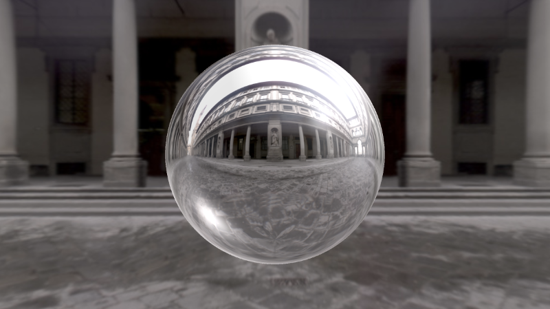
We are using the Phong reflection model we learned in Part 11 and Fresnel reflection we learned in Part 12.
Inside the phong function, we are implementing the Phong reflection model.
1vec3 phong(vec3 lightDir, float lightIntensity, vec3 rd, vec3 normal) {
2 vec3 cubemapReflectionColor = texture(iChannel0, reflect(rd, normal)).rgb;
3
4 vec3 K_a = 1.5 * vec3(0.0,0.5,0.8) * cubemapReflectionColor; // Reflection
5 vec3 K_d = vec3(1);
6 vec3 K_s = vec3(1);
7 float alpha = 50.;
8
9 float diffuse = clamp(dot(lightDir, normal), 0., 1.);
10 float specular = pow(clamp(dot(reflect(lightDir, normal), -rd), 0., 1.), alpha);
11
12 return lightIntensity * (K_a + K_d * diffuse + K_s * specular);
13}The ambient color of the sphere will be the color of the cubemap. However, notice that instead of passing in the ray direction, rd, into the texture function, we are using the reflect function to find the reflected ray direction as if the ray bounced off the sphere. This creates the illusion of a spherical reflection, making the sphere look like a mirror.
1vec3 cubemapReflectionColor = texture(iChannel0, reflect(rd, normal)).rgb;
2vec3 K_a = cubemapReflectionColor;We can also have some fun and add a blue tint to the color of the sphere.
1vec3 cubemapReflectionColor = texture(iChannel0, reflect(rd, normal)).rgb;
2vec3 K_a = 1.5 * vec3(0.0,0.5,0.8) * cubemapReflectionColor;
Beautiful!
How to Use the Cube A Shader
We can create custom cubemaps in Shadertoy by using the “Cube A” option. First, let’s create a new shader. In the previous tutorial, we learned that we can add buffers by clicking the plus sign next to the “Image” tab at the top of the Shadertoy user interface.
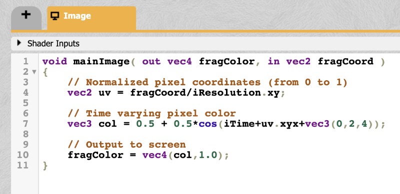
Upon clicking the plus sign, we should see a menu appear. Select the “Cubemap A” option.

When you select the “Cubemap A” option, you should see a new tab appear to the left of the “Image” tab. This tab will say “Cube A.” By default, Shadertoy will provide the following code for this “Cube A” shader.
1void mainCubemap( out vec4 fragColor, in vec2 fragCoord, in vec3 rayOri, in vec3 rayDir )
2{
3 // Ray direction as color
4 vec3 col = 0.5 + 0.5*rayDir;
5
6 // Output to cubemap
7 fragColor = vec4(col,1.0);
8}Instead of defining a mainImage function, we are now defining a mainCubemap function. It automatically provides a ray direction, rayDir, for you. It also provides a ray origin, rayOri in case you need it for performing calculations based on it.
Suppose we want to generate a custom cubemap that is red on opposite faces, blue on opposite faces, and green on opposite faces. Essentially, we’re going to build a dynamic background in the shape of a cube and move the camera around using our mouse. It will look like the following.
We will replace the code in the “Cube A” shader with the following code:
1float max3(vec3 rd) {
2 return max(max(rd.x, rd.y), rd.z);
3}
4
5void mainCubemap( out vec4 fragColor, in vec2 fragCoord, in vec3 rayOri, in vec3 rayDir )
6{
7 vec3 rd = abs(rayDir);
8
9 vec3 col = vec3(0);
10 if (max3(rd) == rd.x) col = vec3(1, 0, 0);
11 if (max3(rd) == rd.y) col = vec3(0, 1, 0);
12 if (max3(rd) == rd.z) col = vec3(0, 0, 1);
13
14 fragColor = vec4(col,1.0); // Output cubemap
15}Let me explain what’s happening here. The max3 function is a function I created for getting the maximum value of each component of a three-dimensional vector, vec3. Inside the mainCubemap function, we’re taking the absolute value of the ray direction, rayDir. Why? If we had a ray direction of vec3(1, 0, 0) and a ray direction of vec3(-1, 0, 0), then we want the pixel color to be red. Thus, opposite faces of the cube will be red.
We’re taking the maximum value of each component of the ray direction to determine which component across the X, Y, and Z axis is larger. This will let us create a “square” shape.
Imagine you’re looking at a cube and calculating the surface normal on each face of the cube. You would end up with six unique surface normals: vec3(1, 0, 0), vec3(0, 1, 0), vec3(0, 0, 1), vec3(-1, 0, 0), vec3(0, -1, 0), vec3(0, 0, -1). By taking the max of the ray direction, we essentially create one of these six surface normals. Since we’re taking the absolute value of the ray direction, we only have to check three different scenarios.
Now that we learned how this code works, let’s go back to the “Image” shader. Click on the iChannel0 box, click the “Misc” tab in the popup menu that appears, and select the “Cubemap A” option.
Then, add the following code to the “Image” shader:
1const float PI = 3.14159265359;
2
3mat2 rotate2d(float theta) {
4 float s = sin(theta), c = cos(theta);
5 return mat2(c, -s, s, c);
6}
7
8mat3 camera(vec3 cameraPos, vec3 lookAtPoint) {
9 vec3 cd = normalize(lookAtPoint - cameraPos);
10 vec3 cr = normalize(cross(vec3(0, 1, 0), cd));
11 vec3 cu = normalize(cross(cd, cr));
12
13 return mat3(-cr, cu, -cd);
14}
15
16void mainImage( out vec4 fragColor, in vec2 fragCoord )
17{
18 vec2 uv = (fragCoord-.5*iResolution.xy)/iResolution.y;
19 vec2 mouseUV = iMouse.xy/iResolution.xy;
20 if (mouseUV == vec2(0.0)) mouseUV = vec2(0.5); // trick to center mouse on page load
21
22 vec3 lp = vec3(0);
23 vec3 ro = vec3(0, 0, 3);
24 ro.yz *= rotate2d(mix(-PI/2., PI/2., mouseUV.y));
25 ro.xz *= rotate2d(mix(-PI, PI, mouseUV.x));
26
27 vec3 rd = camera(ro, lp) * normalize(vec3(uv, -0.5)); // Notice how we're using -0.5 as the zoom factor instead of -1
28
29 vec3 col = texture(iChannel0, rd).rgb;
30
31 fragColor = vec4(col, 1.0);
32}This code is similar to what we used earlier in this tutorial. Instead of using the “Uffizi Gallery” cubemap, we are using the custom cubemap we created in the “Cube A” tab. We also zoomed out a little bit by changing the zoom factor from -1 to -0.5.
1vec3 rd = camera(ro, lp) * normalize(vec3(uv, -0.5));When you run the shader, you should see a colorful background that makes it seem like we’re inside a cube. Neat!
Conclusion
In this tutorial, we learned how to use cubemaps Shadertoy provides and learned how to create our own cubemaps. We can use the texture function to access values stored in a cubemap by using the ray direction. If we want to create reflections, we can use the reflect function together with the ray direction and surface normal to create more realistic reflections. By using the “Cube A” shader, we can create custom cubemaps.
Resources
- Learn OpenGL: Cubemaps
- Shadertoy: How to Use Cubemaps
- Shadertoy: Sphere Reflections with Cubemap
- Shadertoy: How to Use Cubemap A Shader
Snowman Shader in Shadertoy
转自:https://inspirnathan.com/posts/61-snowman-shader-in-shadertoy

Do you wanna build a snowmannnnnnnn ☃️ 🎶?
Come on, let’s go and code.
Trust me, it won’t be a bore.
Prepare your keyboard.
It’s time to ray march awayyyyyyy!!!!
Greetings, friends! You have made it so far on your Shadertoy journey! I’m so proud! Even if you haven’t read any of my past articles and landed here from Google, I’m still proud you visited my website 😃. If you’re new to Shadertoy or even shaders in general, please visit Part 1 of my Shadertoy tutorial series.
In this article, I will show you how to make a snowman shader using the lessons in my Shadertoy tutorial series. We’ll create a simple snowman, add color using structs, and then add lots of details to our scene to create an amazing shader!!!
Initial Setup
We’ll start with the ray marching template we used at the beginning of Part 14 of my Shadertoy tutorial series.
1Do you wanna build a snowmannnnnnnn ☃️ 🎶?
2
3Come on, let's go and code.
4
5Trust me, it won't be a bore.
6
7Prepare your keyboard.
8
9It's time to ray march awayyyyyyy!!!!
10
11Greetings, friends! You have made it so far on your Shadertoy journey! I'm so proud! Even if you haven't read any of my past articles and landed here from Google, I'm still proud you visited my website 😃. If you're new to Shadertoy or even shaders in general, please visit Part 1 of my Shadertoy tutorial series.
12
13In this article, I will show you how to make a snowman shader using the lessons in my Shadertoy tutorial series. We'll create a simple snowman, add color using structs, and then add lots of details to our scene to create an amazing shader!!!
14
15Initial Setup
16We'll start with the ray marching template we used at the beginning of Part 14 of my Shadertoy tutorial series.When you run this code, you should see a sphere appear in the center of the screen. It kinda looks like a snowball, doesn’t it?

Building a Snowman Model
When building 3D models using ray marching, it’s best to think about what SDFs we’ll need to build a snowman. A snowman is typically made using two or three spheres. For our snowman, we’ll keep it simple and build it using only two spheres.
Let’s draw two spheres to the scene. We can use the opUnion function we learned in Part 14 to draw more than one shape to the scene.
1float opUnion(float d1, float d2) {
2 return min(d1, d2);
3}We’ve been using this function already in the previous tutorials. It simply takes the minimum “signed distance” between two SDFs.
1float scene(vec3 p) {
2 float bottomSnowball = sdSphere(p, 1., vec3(0, -1, 0));
3 float topSnowball = sdSphere(p, 0.75, vec3(0, 0.5, 0));
4
5 return opUnion(bottomSnowball, topSnowball);
6}
Right away, you can our snowman starting to take shape, but it looks awkward at the intersection where the two spheres meet. As we learned in Part 14 of my Shadertoy tutorial series, we can blend two shapes smoothly together by using the opSmoothUnion function or smin function, if you want to use a shorter name.
1float opSmoothUnion(float d1, float d2, float k) {
2 float h = clamp( 0.5 + 0.5*(d2-d1)/k, 0.0, 1.0 );
3 return mix( d2, d1, h ) - k*h*(1.0-h);
4}Now, let’s replace the opUnion function with opSmoothUnion in our scene. We’ll use a value of 0.2 as the smoothing factor, k.
1float scene(vec3 p) {
2 float bottomSnowball = sdSphere(p, 1., vec3(0, -1, 0));
3 float topSnowball = sdSphere(p, 0.75, vec3(0, 0.5, 0));
4
5 float d = opSmoothUnion(bottomSnowball, topSnowball, 0.2);
6 return d;
7}
That looks much better! The snowman is missing some eyes though. People tend to give them eyes using buttons or some other round objects. We’ll give our snowman spherical eyes. Let’s start with the left eye.
1float scene(vec3 p) {
2 float bottomSnowball = sdSphere(p, 1., vec3(0, -1, 0));
3 float topSnowball = sdSphere(p, 0.75, vec3(0, 0.5, 0));
4 float leftEye = sdSphere(p, .1, vec3(-0.2, 0.6, 0.7));
5
6 float d = opSmoothUnion(bottomSnowball, topSnowball, 0.2);
7 d = opUnion(d, leftEye);
8 return d;
9}
The right eye will use the same offset value as the left eye except the x-axis will be mirrored.
1float scene(vec3 p) {
2 float bottomSnowball = sdSphere(p, 1., vec3(0, -1, 0));
3 float topSnowball = sdSphere(p, 0.75, vec3(0, 0.5, 0));
4 float leftEye = sdSphere(p, .1, vec3(-0.2, 0.6, 0.7));
5 float rightEye = sdSphere(p, .1, vec3(0.2, 0.6, 0.7));
6
7 float d = opSmoothUnion(bottomSnowball, topSnowball, 0.2);
8 d = opUnion(d, leftEye);
9 d = opUnion(d, rightEye);
10 return d;
11}
Next, the snowman needs a nose. People tend to make noses for snowmen out of carrots. We can simulate a carrot nose by using a cone SDF from Inigo Quilez’s list of 3D SDFs. We’ll choose the SDF called “Cone - bound (not exact)” which has the following function declaration:
1float sdCone( vec3 p, vec2 c, float h )
2{
3 float q = length(p.xz);
4 return max(dot(c.xy,vec2(q,p.y)),-h-p.y);
5}This is for a cone pointing straight up. We want the tip of the cone to face us, toward the positive z-axis. To switch this, we’ll replace p.xz with p.xy and replace p.y with p.z.
1float sdCone( vec3 p, vec2 c, float h )
2{
3 p -= offset;
4 float q = length(p.xy);
5 return max(dot(c.xy,vec2(q,p.z)),-h-p.z);
6}We also need to add an offset parameter to this function, so we can move the cone around in 3D space. Therefore, we end up with the following function declaration for the cone SDF.
1float sdCone( vec3 p, vec2 c, float h, vec3 offset )
2{
3 p -= offset;
4 float q = length(p.xy);
5 return max(dot(c.xy,vec2(q,p.z)),-h-p.z);
6}To use this SDF, we need to create an angle for the cone. This requires playing around with the value a bit. A value of 75 degrees seems to work fine. You can use the radians function that is built into the GLSL language to convert a number from degrees to radians. The parameters, c and h, are used to control the dimensions of the cone.
Let’s add a nose to our snowman!
1float scene(vec3 p) {
2 float bottomSnowball = sdSphere(p, 1., vec3(0, -1, 0));
3 float topSnowball = sdSphere(p, 0.75, vec3(0, 0.5, 0));
4
5 float leftEye = sdSphere(p, .1, vec3(-0.2, 0.6, 0.7));
6 float rightEye = sdSphere(p, .1, vec3(0.2, 0.6, 0.7));
7
8 float noseAngle = radians(75.);
9 float nose = sdCone(p, vec2(sin(noseAngle), cos(noseAngle)), 0.5, vec3(0, 0.4, 1.2));
10
11 float d = opSmoothUnion(bottomSnowball, topSnowball, 0.2);
12 d = opUnion(d, leftEye);
13 d = opUnion(d, rightEye);
14 d = opUnion(d, nose);
15 return d;
16}
You can use your mouse to move the camera around the snowman to make sure the cone looks fine.

Let’s add arms to the snowman. Typically, the arms are made of sticks. We can simulate sticks by using a 3D line or “capsule.” In Inigo Quilez’s list of 3D SDFs, there’s an SDF called “Capsule / Line - exact” that we can leverage for building a snowman arm.
1float sdCapsule( vec3 p, vec3 a, vec3 b, float r )
2{
3 vec3 pa = p - a, ba = b - a;
4 float h = clamp( dot(pa,ba)/dot(ba,ba), 0.0, 1.0 );
5 return length( pa - ba*h ) - r;
6}Add an offset parameter to this function, so we can move the capsule around in 3D space.
1float sdCapsule( vec3 p, vec3 a, vec3 b, float r, vec3 offset )
2{
3 p -= offset;
4 vec3 pa = p - a, ba = b - a;
5 float h = clamp( dot(pa,ba)/dot(ba,ba), 0.0, 1.0 );
6 return length( pa - ba*h ) - r;
7}Then, we’ll add a capsule in our 3D scene to simulate the left arm of the snowman.
1float scene(vec3 p) {
2 float bottomSnowball = sdSphere(p, 1., vec3(0, -1, 0));
3 float topSnowball = sdSphere(p, 0.75, vec3(0, 0.5, 0));
4
5 float leftEye = sdSphere(p, .1, vec3(-0.2, 0.6, 0.7));
6 float rightEye = sdSphere(p, .1, vec3(0.2, 0.6, 0.7));
7
8 float noseAngle = radians(75.);
9 float nose = sdCone(p, vec2(sin(noseAngle), cos(noseAngle)), 0.5, vec3(0, 0.4, 1.2));
10
11 float mainBranch = sdCapsule(p, vec3(0, 0.5, 0), vec3(0.8, 0, 0.), 0.05, vec3(-1.5, -0.5, 0));
12
13 float d = opSmoothUnion(bottomSnowball, topSnowball, 0.2);
14 d = opUnion(d, leftEye);
15 d = opUnion(d, rightEye);
16 d = opUnion(d, nose);
17 d = opUnion(d, mainBranch);
18 return d;
19}
The arm looks a bit too small and kinda awkward. Let’s add a couple small capsules that branch off the “main branch” arm, so that it looks like the arm is built out of a tree branch.
1float scene(vec3 p) {
2 float bottomSnowball = sdSphere(p, 1., vec3(0, -1, 0));
3 float topSnowball = sdSphere(p, 0.75, vec3(0, 0.5, 0));
4
5 float leftEye = sdSphere(p, .1, vec3(-0.2, 0.6, 0.7));
6 float rightEye = sdSphere(p, .1, vec3(0.2, 0.6, 0.7));
7
8 float noseAngle = radians(75.);
9 float nose = sdCone(p, vec2(sin(noseAngle), cos(noseAngle)), 0.5, vec3(0, 0.4, 1.2));
10
11 float mainBranch = sdCapsule(p, vec3(0, 0.5, 0), vec3(0.8, 0, 0.), 0.05, vec3(-1.5, -0.5, 0));
12 float smallBranchBottom = sdCapsule(p, vec3(0, 0.1, 0), vec3(0.5, 0, 0.), 0.05, vec3(-2, 0, 0));
13 float smallBranchTop = sdCapsule(p, vec3(0, 0.3, 0), vec3(0.5, 0, 0.), 0.05, vec3(-2, 0, 0));
14
15 float d = opSmoothUnion(bottomSnowball, topSnowball, 0.2);
16 d = opUnion(d, leftEye);
17 d = opUnion(d, rightEye);
18 d = opUnion(d, nose);
19 d = opUnion(d, mainBranch);
20 d = opUnion(d, smallBranchBottom);
21 d = opUnion(d, smallBranchTop);
22 return d;
23}
For the right arm, we need to apply the same three capsule SDFs but flip the sign of the x-component to “mirror” the arm on the other side of the snowman. We could write another three lines for the right arm, one for each capsule SDF, or we can get clever. The snowman is currently centered in the middle of our screen. We can take advantage of symmetry to draw the right arm with the same offset as the left arm but with a positive x-component instead of negative.
Let’s create a custom SDF that merges the three branches into one SDF called sdArm.
1float sdArm(vec3 p) {
2 float mainBranch = sdCapsule(p, vec3(0, 0.5, 0), vec3(0.8, 0, 0.), 0.05, vec3(-1.5, -0.5, 0));
3 float smallBranchBottom = sdCapsule(p, vec3(0, 0.1, 0), vec3(0.5, 0, 0.), 0.05, vec3(-2, 0, 0));
4 float smallBranchTop = sdCapsule(p, vec3(0, 0.3, 0), vec3(0.5, 0, 0.), 0.05, vec3(-2, 0, 0));
5
6 float d = opUnion(mainBranch, smallBranchBottom);
7 d = opUnion(d, smallBranchTop);
8 return d;
9}Then, we can use this function inside our scene function.
1float scene(vec3 p) {
2 float bottomSnowball = sdSphere(p, 1., vec3(0, -1, 0));
3 float topSnowball = sdSphere(p, 0.75, vec3(0, 0.5, 0));
4
5 float leftEye = sdSphere(p, .1, vec3(-0.2, 0.6, 0.7));
6 float rightEye = sdSphere(p, .1, vec3(0.2, 0.6, 0.7));
7
8 float noseAngle = radians(75.);
9 float nose = sdCone(p, vec2(sin(noseAngle), cos(noseAngle)), 0.5, vec3(0, 0.4, 1.2));
10
11 float leftArm = sdArm(p);
12
13 float d = opSmoothUnion(bottomSnowball, topSnowball, 0.2);
14 d = opUnion(d, leftEye);
15 d = opUnion(d, rightEye);
16 d = opUnion(d, nose);
17 d = opUnion(d, leftArm);
18 return d;
19}Let’s make a custom operation called opFlipX that will flip the sign of the x-component of the point passed into it.
1vec3 opFlipX(vec3 p) {
2 p.x *= -1.;
3 return p;
4}Then, we can use this function inside the scene function to draw the right arm.
1float scene(vec3 p) {
2 float bottomSnowball = sdSphere(p, 1., vec3(0, -1, 0));
3 float topSnowball = sdSphere(p, 0.75, vec3(0, 0.5, 0));
4
5 float leftEye = sdSphere(p, .1, vec3(-0.2, 0.6, 0.7));
6 float rightEye = sdSphere(p, .1, vec3(0.2, 0.6, 0.7));
7
8 float noseAngle = radians(75.);
9 float nose = sdCone(p, vec2(sin(noseAngle), cos(noseAngle)), 0.5, vec3(0, 0.4, 1.2));
10
11 float leftArm = sdArm(p);
12 float rightArm = sdArm(opFlipX(p));
13
14 float d = opSmoothUnion(bottomSnowball, topSnowball, 0.2);
15 d = opUnion(d, leftEye);
16 d = opUnion(d, rightEye);
17 d = opUnion(d, nose);
18 d = opUnion(d, leftArm);
19 d = opUnion(d, rightArm);
20 return d;
21}
Voilà! We used symmetry to draw the right arm of the snowman! If we decide to move the arm a bit, it’ll automatically be reflected in the offset of the right arm.
We can use the new opFlipX operation for the right eye of the snowman as well. Let’s create a custom SDF for an eye of the snowman.
1float sdEye(vec3 p) {
2 return sdSphere(p, .1, vec3(-0.2, 0.6, 0.7));
3}Next, we can use it inside the scene function to draw both the left eye and right eye.
1float scene(vec3 p) {
2 float bottomSnowball = sdSphere(p, 1., vec3(0, -1, 0));
3 float topSnowball = sdSphere(p, 0.75, vec3(0, 0.5, 0));
4
5 float leftEye = sdEye(p);
6 float rightEye = sdEye(opFlipX(p));
7
8 float noseAngle = radians(75.);
9 float nose = sdCone(p, vec2(sin(noseAngle), cos(noseAngle)), 0.5, vec3(0, 0.4, 1.2));
10
11 float leftArm = sdArm(p);
12 float rightArm = sdArm(opFlipX(p));
13
14 float d = opSmoothUnion(bottomSnowball, topSnowball, 0.2);
15 d = opUnion(d, leftEye);
16 d = opUnion(d, rightEye);
17 d = opUnion(d, nose);
18 d = opUnion(d, leftArm);
19 d = opUnion(d, rightArm);
20 return d;
21}The snowman looks great so far, but it’s missing some pizazz. It could be great if the snowman had a top hat. We can simulate a top hat by combining two cylinders together. For that, we’ll need to grab the cylinder SDF titled “Capped Cylinder - exact” from Inigo Quilez’s list of 3D SDFs.
1float sdCappedCylinder( vec3 p, float h, float r )
2{
3 vec2 d = abs(vec2(length(p.xz),p.y)) - vec2(h,r);
4 return min(max(d.x,d.y),0.0) + length(max(d,0.0));
5}Make sure to add an offset, so we can move the hat around in 3D space.
1float sdCappedCylinder( vec3 p, float h, float r, vec3 offset )
2{
3 p -= offset;
4 vec2 d = abs(vec2(length(p.xz),p.y)) - vec2(h,r);
5 return min(max(d.x,d.y),0.0) + length(max(d,0.0));
6}We can create a thin cylinder for the bottom part of the hat, and a tall cylinder for the top part of the hat.
1float scene(vec3 p) {
2 float bottomSnowball = sdSphere(p, 1., vec3(0, -1, 0));
3 float topSnowball = sdSphere(p, 0.75, vec3(0, 0.5, 0));
4
5 float leftEye = sdEye(p);
6 float rightEye = sdEye(opFlipX(p));
7
8 float noseAngle = radians(75.);
9 float nose = sdCone(p, vec2(sin(noseAngle), cos(noseAngle)), 0.5, vec3(0, 0.4, 1.2));
10
11 float leftArm = sdArm(p);
12 float rightArm = sdArm(opFlipX(p));
13
14 float hatBottom = sdCappedCylinder(p, 0.5, 0.05, vec3(0, 1.2, 0));
15 float hatTop = sdCappedCylinder(p, 0.3, 0.3, vec3(0, 1.5, 0));
16
17 float d = opSmoothUnion(bottomSnowball, topSnowball, 0.2);
18 d = opUnion(d, leftEye);
19 d = opUnion(d, rightEye);
20 d = opUnion(d, nose);
21 d = opUnion(d, leftArm);
22 d = opUnion(d, rightArm);
23 d = opUnion(d, hatBottom);
24 d = opUnion(d, hatTop);
25 return d;
26}
Our snowman is looking dapper now! 😃
Organizing Code with Custom SDFs
When we color the snowman, we’ll need to target the individual parts of the snowman that have unique colors. We can organize the code by creating custom SDFs for each part of the snowman that will have a unique color.
Let’s create an SDF called sdBody for the body of the snowman.
1float sdBody(vec3 p) {
2 float bottomSnowball = sdSphere(p, 1., vec3(0, -1, 0));
3 float topSnowball = sdSphere(p, 0.75, vec3(0, 0.5, 0));
4
5 return opSmoothUnion(bottomSnowball, topSnowball, 0.2);
6}We already created an SDF for the eyes called sdEyes, but we need to create an SDF for the nose. Create a new function called sdNose with the following contents.
1float sdNose(vec3 p) {
2 float noseAngle = radians(75.);
3 return sdCone(p, vec2(sin(noseAngle), cos(noseAngle)), 0.5, vec3(0, 0.4, 1.2));
4}We already created a custom SDF for the arms, but let’s create one for the hat called sdHat with the following code.
1float sdHat(vec3 p) {
2 float hatBottom = sdCappedCylinder(p, 0.5, 0.05, vec3(0, 1.2, 0));
3 float hatTop = sdCappedCylinder(p, 0.3, 0.3, vec3(0, 1.5, 0));
4
5 return opUnion(hatBottom, hatTop);
6}Now, we can adjust our scene function to use all of our custom SDFs that already take account for the offset or position of each part of the snowman inside the function declaration.
1float scene(vec3 p) {
2 float body = sdBody(p);
3 float leftEye = sdEye(p);
4 float rightEye = sdEye(opFlipX(p));
5 float nose = sdNose(p);
6 float leftArm = sdArm(p);
7 float rightArm = sdArm(opFlipX(p));
8 float hat = sdHat(p);
9
10 float d = body;
11 d = opUnion(d, leftEye);
12 d = opUnion(d, rightEye);
13 d = opUnion(d, nose);
14 d = opUnion(d, leftArm);
15 d = opUnion(d, rightArm);
16 d = opUnion(d, hat);
17 return d;
18}Looks much cleaner now! There’s one more thing we can do to make this code a bit more abstract. If we plan on drawing multiple snowmen to the scene, then we should create a custom SDF that draws an entire snowman. Let’s create a new function called sdSnowman that does just that.
1float sdSnowman(vec3 p) {
2 float body = sdBody(p);
3 float leftEye = sdEye(p);
4 float rightEye = sdEye(opFlipX(p));
5 float nose = sdNose(p);
6 float leftArm = sdArm(p);
7 float rightArm = sdArm(opFlipX(p));
8 float hat = sdHat(p);
9
10 float d = body;
11 d = opUnion(d, leftEye);
12 d = opUnion(d, rightEye);
13 d = opUnion(d, nose);
14 d = opUnion(d, leftArm);
15 d = opUnion(d, rightArm);
16 d = opUnion(d, hat);
17 return d;
18}Finally, our scene function will simply return the value of snowman SDF.
1float scene(vec3 p) {
2 return sdSnowman(p);
3}Our snowman is now built and ready to be colored! You can find the finished code for this entire scene below.
1const int MAX_MARCHING_STEPS = 255;
2const float MIN_DIST = 0.0;
3const float MAX_DIST = 100.0;
4const float PRECISION = 0.001;
5const float EPSILON = 0.0005;
6const float PI = 3.14159265359;
7const vec3 COLOR_BACKGROUND = vec3(.741, .675, .82);
8const vec3 COLOR_AMBIENT = vec3(0.42, 0.20, 0.1);
9
10mat2 rotate2d(float theta) {
11 float s = sin(theta), c = cos(theta);
12 return mat2(c, -s, s, c);
13}
14
15float opUnion(float d1, float d2) {
16 return min(d1, d2);
17}
18
19float opSmoothUnion(float d1, float d2, float k) {
20 float h = clamp( 0.5 + 0.5*(d2-d1)/k, 0.0, 1.0 );
21 return mix( d2, d1, h ) - k*h*(1.0-h);
22}
23
24vec3 opFlipX(vec3 p) {
25 p.x *= -1.;
26 return p;
27}
28
29float sdSphere(vec3 p, float r, vec3 offset)
30{
31 return length(p - offset) - r;
32}
33
34float sdCone( vec3 p, vec2 c, float h, vec3 offset )
35{
36 p -= offset;
37 float q = length(p.xy);
38 return max(dot(c.xy,vec2(q,p.z)),-h-p.z);
39}
40
41float sdCapsule( vec3 p, vec3 a, vec3 b, float r, vec3 offset )
42{
43 p -= offset;
44 vec3 pa = p - a, ba = b - a;
45 float h = clamp( dot(pa,ba)/dot(ba,ba), 0.0, 1.0 );
46 return length( pa - ba*h ) - r;
47}
48
49float sdCappedCylinder( vec3 p, float h, float r, vec3 offset )
50{
51 p -= offset;
52 vec2 d = abs(vec2(length(p.xz),p.y)) - vec2(h,r);
53 return min(max(d.x,d.y),0.0) + length(max(d,0.0));
54}
55
56float sdBody(vec3 p) {
57 float bottomSnowball = sdSphere(p, 1., vec3(0, -1, 0));
58 float topSnowball = sdSphere(p, 0.75, vec3(0, 0.5, 0));
59
60 return opSmoothUnion(bottomSnowball, topSnowball, 0.2);
61}
62
63float sdEye(vec3 p) {
64 return sdSphere(p, .1, vec3(-0.2, 0.6, 0.7));
65}
66
67float sdNose(vec3 p) {
68 float noseAngle = radians(75.);
69 return sdCone(p, vec2(sin(noseAngle), cos(noseAngle)), 0.5, vec3(0, 0.4, 1.2));
70}
71
72float sdArm(vec3 p) {
73 float mainBranch = sdCapsule(p, vec3(0, 0.5, 0), vec3(0.8, 0, 0.), 0.05, vec3(-1.5, -0.5, 0));
74 float smallBranchBottom = sdCapsule(p, vec3(0, 0.1, 0), vec3(0.5, 0, 0.), 0.05, vec3(-2, 0, 0));
75 float smallBranchTop = sdCapsule(p, vec3(0, 0.3, 0), vec3(0.5, 0, 0.), 0.05, vec3(-2, 0, 0));
76
77 float d = opUnion(mainBranch, smallBranchBottom);
78 d = opUnion(d, smallBranchTop);
79 return d;
80}
81
82float sdHat(vec3 p) {
83 float hatBottom = sdCappedCylinder(p, 0.5, 0.05, vec3(0, 1.2, 0));
84 float hatTop = sdCappedCylinder(p, 0.3, 0.3, vec3(0, 1.5, 0));
85
86 return opUnion(hatBottom, hatTop);
87}
88
89float sdSnowman(vec3 p) {
90 float body = sdBody(p);
91 float leftEye = sdEye(p);
92 float rightEye = sdEye(opFlipX(p));
93 float nose = sdNose(p);
94 float leftArm = sdArm(p);
95 float rightArm = sdArm(opFlipX(p));
96 float hat = sdHat(p);
97
98 float d = body;
99 d = opUnion(d, leftEye);
100 d = opUnion(d, rightEye);
101 d = opUnion(d, nose);
102 d = opUnion(d, leftArm);
103 d = opUnion(d, rightArm);
104 d = opUnion(d, hat);
105 return d;
106}
107
108float scene(vec3 p) {
109 return sdSnowman(p);
110}
111
112float rayMarch(vec3 ro, vec3 rd) {
113 float depth = MIN_DIST;
114 float d; // distance ray has travelled
115
116 for (int i = 0; i < MAX_MARCHING_STEPS; i++) {
117 vec3 p = ro + depth * rd;
118 d = scene(p);
119 depth += d;
120 if (d < PRECISION || depth > MAX_DIST) break;
121 }
122
123 d = depth;
124
125 return d;
126}
127
128vec3 calcNormal(in vec3 p) {
129 vec2 e = vec2(1, -1) * EPSILON;
130 return normalize(
131 e.xyy * scene(p + e.xyy) +
132 e.yyx * scene(p + e.yyx) +
133 e.yxy * scene(p + e.yxy) +
134 e.xxx * scene(p + e.xxx));
135}
136
137mat3 camera(vec3 cameraPos, vec3 lookAtPoint) {
138 vec3 cd = normalize(lookAtPoint - cameraPos);
139 vec3 cr = normalize(cross(vec3(0, 1, 0), cd));
140 vec3 cu = normalize(cross(cd, cr));
141
142 return mat3(-cr, cu, -cd);
143}
144
145void mainImage( out vec4 fragColor, in vec2 fragCoord )
146{
147 vec2 uv = (fragCoord-.5*iResolution.xy)/iResolution.y;
148 vec2 mouseUV = iMouse.xy/iResolution.xy;
149
150 if (mouseUV == vec2(0.0)) mouseUV = vec2(0.5); // trick to center mouse on page load
151
152 vec3 col = vec3(0);
153 vec3 lp = vec3(0); // lookat point
154 vec3 ro = vec3(0, 0, 3); // ray origin that represents camera position
155
156 float cameraRadius = 2.;
157 ro.yz = ro.yz * cameraRadius * rotate2d(mix(-PI/2., PI/2., mouseUV.y));
158 ro.xz = ro.xz * rotate2d(mix(-PI, PI, mouseUV.x)) + vec2(lp.x, lp.z);
159
160 vec3 rd = camera(ro, lp) * normalize(vec3(uv, -1)); // ray direction
161
162 float d = rayMarch(ro, rd); // signed distance value to closest object
163
164 if (d > MAX_DIST) {
165 col = COLOR_BACKGROUND; // ray didn't hit anything
166 } else {
167 vec3 p = ro + rd * d; // point discovered from ray marching
168 vec3 normal = calcNormal(p); // surface normal
169
170 vec3 lightPosition = vec3(0, 2, 2);
171 vec3 lightDirection = normalize(lightPosition - p) * .65; // The 0.65 is used to decrease the light intensity a bit
172
173 float dif = clamp(dot(normal, lightDirection), 0., 1.) * 0.5 + 0.5; // diffuse reflection mapped to values between 0.5 and 1.0
174
175 col = vec3(dif) + COLOR_AMBIENT;
176 }
177
178 fragColor = vec4(col, 1.0);
179}Coloring the Snowman
Now that we have the model of snowman built, let’s add some color! We can declare some constants at the top of our code. We already have constants declared for the background color and ambient color in our scene. Let’s add colors for each part of the snowman.
1const vec3 COLOR_BACKGROUND = vec3(.741, .675, .82);
2const vec3 COLOR_AMBIENT = vec3(0.42, 0.20, 0.1);
3const vec3 COLOR_BODY = vec3(1);
4const vec3 COLOR_EYE = vec3(0);
5const vec3 COLOR_NOSE = vec3(0.8, 0.3, 0.1);
6const vec3 COLOR_ARM = vec3(0.2);
7const vec3 COLOR_HAT = vec3(0);Take note that the final color of the snowman is currently determined by Lambertian diffuse reflection plus the ambient color. Therefore, the color we defined in our constants will be blended with the ambient color. If you prefer, you can remove the ambient color to see the true color of each part of the snowman.
1float dif = clamp(dot(normal, lightDirection), 0., 1.) * 0.5 + 0.5;
2col = vec3(dif) + COLOR_AMBIENT; As we learned in Part 7 of my Shadertoy tutorial series, we can use structs to hold multiple values. We’ll create a new struct that will hold the “signed distance” from the camera to the surface of an object in our scene and the color of that surface.
1struct Surface {
2 float sd; // signed distance
3 vec3 col; // diffuse color
4};We’ll have to make changes to a few operations, so they return Surface structs instead of just float values.
For the opUnion operation, we will actually overload this function. We’ll keep the original function intact, but create a new opUnion function that passes in Surface structs instead of floats.
1float opUnion(float d1, float d2) {
2 return min(d1, d2);
3}
4
5Surface opUnion(Surface d1, Surface d2) {
6 if (d2.sd < d1.sd) return d2;
7 return d1;
8}Function overloading is quite common across different programming languages. It lets us define the same function name, but we can pass in a different number of parameters or different types of parameters. Therefore, if we call opUnion with float values, then it’ll call the first function definition. If we call opUnion with Surface structs, then it’ll call the second definition.
For the opSmoothUnion function, we won’t need to overload this function. We will change this function to accept Surface structs instead of float values. Therefore, we need to call mix on both the signed distance, sd, and the color, col. This lets us smoothly blend two shapes together and blend their colors together as well.
1Surface opSmoothUnion( Surface d1, Surface d2, float k ) {
2 Surface s;
3 float h = clamp( 0.5 + 0.5*(d2.sd-d1.sd)/k, 0.0, 1.0 );
4 s.sd = mix( d2.sd, d1.sd, h ) - k*h*(1.0-h);
5 s.col = mix( d2.col, d1.col, h ) - k*h*(1.0-h);
6
7 return s;
8}We’ll leave the SDFs for the primitive shapes (sphere, cone, capsule, cylinder) alone. They will continue to return a float value. However, we’ll need to adjust our custom SDFs that return a part of the snowman. We want to return a Surface struct that contains a color for each part of our snowman, so we can pass along the color value during our ray marching loop.
1Surface sdBody(vec3 p) {
2 Surface bottomSnowball = Surface(sdSphere(p, 1., vec3(0, -1, 0)), COLOR_BODY);
3 Surface topSnowball = Surface(sdSphere(p, 0.75, vec3(0, 0.5, 0)), COLOR_BODY);
4
5 return opSmoothUnion(bottomSnowball, topSnowball, 0.2);
6}
7
8Surface sdEye(vec3 p) {
9 float d = sdSphere(p, .1, vec3(-0.2, 0.6, 0.7));
10 return Surface(d, COLOR_EYE);
11}
12
13Surface sdNose(vec3 p) {
14 float noseAngle = radians(75.);
15 float d = sdCone(p, vec2(sin(noseAngle), cos(noseAngle)), 0.5, vec3(0, 0.4, 1.2));
16 return Surface(d, COLOR_NOSE);
17}
18
19Surface sdArm(vec3 p) {
20 float mainBranch = sdCapsule(p, vec3(0, 0.5, 0), vec3(0.8, 0, 0.), 0.05, vec3(-1.5, -0.5, 0));
21 float smallBranchBottom = sdCapsule(p, vec3(0, 0.1, 0), vec3(0.5, 0, 0.), 0.05, vec3(-2, 0, 0));
22 float smallBranchTop = sdCapsule(p, vec3(0, 0.3, 0), vec3(0.5, 0, 0.), 0.05, vec3(-2, 0, 0));
23
24 float d = opUnion(mainBranch, smallBranchBottom);
25 d = opUnion(d, smallBranchTop);
26 return Surface(d, COLOR_ARM);
27}
28
29Surface sdHat(vec3 p) {
30 Surface bottom = Surface(sdCappedCylinder(p, 0.5, 0.05, vec3(0, 1.2, 0)), COLOR_HAT);
31 Surface top = Surface(sdCappedCylinder(p, 0.3, 0.3, vec3(0, 1.5, 0)), COLOR_HAT);
32
33 return opUnion(bottom, top);
34}
35
36Surface sdSnowman(vec3 p) {
37 Surface body = sdBody(p);
38 Surface leftEye = sdEye(p);
39 Surface rightEye = sdEye(opFlipX(p));
40 Surface nose = sdNose(p);
41 Surface leftArm = sdArm(p);
42 Surface rightArm = sdArm(opFlipX(p));
43 Surface hat = sdHat(p);
44
45 Surface co = body;
46 co = opUnion(co, leftEye);
47 co = opUnion(co, rightEye);
48 co = opUnion(co, nose);
49 co = opUnion(co, hat);
50 co = opUnion(co, leftArm);
51 co = opUnion(co, rightArm);
52
53 return co;
54}
55
56Surface scene(vec3 p) {
57 return sdSnowman(p);
58}Our ray marching loop will need adjusted, since we are now returning a Surface struct instead of a float value.
1Surface rayMarch(vec3 ro, vec3 rd) {
2 float depth = MIN_DIST;
3 Surface co; // closest object
4
5 for (int i = 0; i < MAX_MARCHING_STEPS; i++) {
6 vec3 p = ro + depth * rd;
7 co = scene(p);
8 depth += co.sd;
9 if (co.sd < PRECISION || depth > MAX_DIST) break;
10 }
11
12 co.sd = depth;
13
14 return co;
15}We also need to adjust the calcNormal function to use the signed distance value, sd.
1vec3 calcNormal(in vec3 p) {
2 vec2 e = vec2(1, -1) * EPSILON;
3 return normalize(
4 e.xyy * scene(p + e.xyy).sd +
5 e.yyx * scene(p + e.yyx).sd +
6 e.yxy * scene(p + e.yxy).sd +
7 e.xxx * scene(p + e.xxx).sd);
8}In the mainImage function, the ray marching loop used to return a float.
1float d = rayMarch(ro, rd);We need to replace the above code with the following, since the ray marching loop now returns a Surface struct.
1Surface co = rayMarch(ro, rd);Additionally, we need to check if co.sd is greater than MAX_DIST instead of d:
1if (co.sd > MAX_DIST)Likewise, we need to use co instead of d when defining p:
1vec3 p = ro + rd * co.sd;In the mainImage function, we were setting the color equal to the diffuse color plus the ambient color.
1col = vec3(dif) + COLOR_AMBIENT;Now, we need to replace the above line with the following, since the color is determined by the part of the snowman hit by the ray as well.
1col = dif * co.col + COLOR_AMBIENT;Your finished code should look like the following:
1const int MAX_MARCHING_STEPS = 255;
2const float MIN_DIST = 0.0;
3const float MAX_DIST = 100.0;
4const float PRECISION = 0.001;
5const float EPSILON = 0.0005;
6const float PI = 3.14159265359;
7const vec3 COLOR_BACKGROUND = vec3(.741, .675, .82);
8const vec3 COLOR_AMBIENT = vec3(0.42, 0.20, 0.1);
9const vec3 COLOR_BODY = vec3(1);
10const vec3 COLOR_EYE = vec3(0);
11const vec3 COLOR_NOSE = vec3(0.8, 0.3, 0.1);
12const vec3 COLOR_ARM = vec3(0.2);
13const vec3 COLOR_HAT = vec3(0);
14
15struct Surface {
16 float sd; // signed distance
17 vec3 col; // diffuse color
18};
19
20mat2 rotate2d(float theta) {
21 float s = sin(theta), c = cos(theta);
22 return mat2(c, -s, s, c);
23}
24
25float opUnion(float d1, float d2) {
26 return min(d1, d2);
27}
28
29Surface opUnion(Surface d1, Surface d2) {
30 if (d2.sd < d1.sd) return d2;
31 return d1;
32}
33
34Surface opSmoothUnion( Surface d1, Surface d2, float k ) {
35 Surface s;
36 float h = clamp( 0.5 + 0.5*(d2.sd-d1.sd)/k, 0.0, 1.0 );
37 s.sd = mix( d2.sd, d1.sd, h ) - k*h*(1.0-h);
38 s.col = mix( d2.col, d1.col, h ) - k*h*(1.0-h);
39
40 return s;
41}
42
43vec3 opFlipX(vec3 p) {
44 p.x *= -1.;
45 return p;
46}
47
48float sdSphere(vec3 p, float r, vec3 offset)
49{
50 return length(p - offset) - r;
51}
52
53float sdCone( vec3 p, vec2 c, float h, vec3 offset )
54{
55 p -= offset;
56 float q = length(p.xy);
57 return max(dot(c.xy,vec2(q,p.z)),-h-p.z);
58}
59
60float sdCapsule( vec3 p, vec3 a, vec3 b, float r, vec3 offset )
61{
62 p -= offset;
63 vec3 pa = p - a, ba = b - a;
64 float h = clamp( dot(pa,ba)/dot(ba,ba), 0.0, 1.0 );
65 return length( pa - ba*h ) - r;
66}
67
68float sdCappedCylinder(vec3 p, float h, float r, vec3 offset)
69{
70 p -= offset;
71 vec2 d = abs(vec2(length(p.xz),p.y)) - vec2(h,r);
72 return min(max(d.x,d.y),0.0) + length(max(d,0.0));
73}
74
75Surface sdBody(vec3 p) {
76 Surface bottomSnowball = Surface(sdSphere(p, 1., vec3(0, -1, 0)), COLOR_BODY);
77 Surface topSnowball = Surface(sdSphere(p, 0.75, vec3(0, 0.5, 0)), COLOR_BODY);
78
79 return opSmoothUnion(bottomSnowball, topSnowball, 0.2);
80}
81
82Surface sdEye(vec3 p) {
83 float d = sdSphere(p, .1, vec3(-0.2, 0.6, 0.7));
84 return Surface(d, COLOR_EYE);
85}
86
87Surface sdNose(vec3 p) {
88 float noseAngle = radians(75.);
89 float d = sdCone(p, vec2(sin(noseAngle), cos(noseAngle)), 0.5, vec3(0, 0.4, 1.2));
90 return Surface(d, COLOR_NOSE);
91}
92
93Surface sdArm(vec3 p) {
94 float mainBranch = sdCapsule(p, vec3(0, 0.5, 0), vec3(0.8, 0, 0.), 0.05, vec3(-1.5, -0.5, 0));
95 float smallBranchBottom = sdCapsule(p, vec3(0, 0.1, 0), vec3(0.5, 0, 0.), 0.05, vec3(-2, 0, 0));
96 float smallBranchTop = sdCapsule(p, vec3(0, 0.3, 0), vec3(0.5, 0, 0.), 0.05, vec3(-2, 0, 0));
97
98 float d = opUnion(mainBranch, smallBranchBottom);
99 d = opUnion(d, smallBranchTop);
100 return Surface(d, COLOR_ARM);
101}
102
103Surface sdHat(vec3 p) {
104 Surface bottom = Surface(sdCappedCylinder(p, 0.5, 0.05, vec3(0, 1.2, 0)), COLOR_HAT);
105 Surface top = Surface(sdCappedCylinder(p, 0.3, 0.3, vec3(0, 1.5, 0)), COLOR_HAT);
106
107 return opUnion(bottom, top);
108}
109
110Surface sdSnowman(vec3 p) {
111 Surface body = sdBody(p);
112 Surface leftEye = sdEye(p);
113 Surface rightEye = sdEye(opFlipX(p));
114 Surface nose = sdNose(p);
115 Surface leftArm = sdArm(p);
116 Surface rightArm = sdArm(opFlipX(p));
117 Surface hat = sdHat(p);
118
119 Surface co = body;
120 co = opUnion(co, leftEye);
121 co = opUnion(co, rightEye);
122 co = opUnion(co, nose);
123 co = opUnion(co, hat);
124 co = opUnion(co, leftArm);
125 co = opUnion(co, rightArm);
126
127 return co;
128}
129
130Surface scene(vec3 p) {
131 return sdSnowman(p);
132}
133
134Surface rayMarch(vec3 ro, vec3 rd) {
135 float depth = MIN_DIST;
136 Surface co; // closest object
137
138 for (int i = 0; i < MAX_MARCHING_STEPS; i++) {
139 vec3 p = ro + depth * rd;
140 co = scene(p);
141 depth += co.sd;
142 if (co.sd < PRECISION || depth > MAX_DIST) break;
143 }
144
145 co.sd = depth;
146
147 return co;
148}
149
150vec3 calcNormal(in vec3 p) {
151 vec2 e = vec2(1, -1) * EPSILON;
152 return normalize(
153 e.xyy * scene(p + e.xyy).sd +
154 e.yyx * scene(p + e.yyx).sd +
155 e.yxy * scene(p + e.yxy).sd +
156 e.xxx * scene(p + e.xxx).sd);
157}
158
159mat3 camera(vec3 cameraPos, vec3 lookAtPoint) {
160 vec3 cd = normalize(lookAtPoint - cameraPos);
161 vec3 cr = normalize(cross(vec3(0, 1, 0), cd));
162 vec3 cu = normalize(cross(cd, cr));
163
164 return mat3(-cr, cu, -cd);
165}
166
167void mainImage( out vec4 fragColor, in vec2 fragCoord )
168{
169 vec2 uv = (fragCoord-.5*iResolution.xy)/iResolution.y;
170 vec2 mouseUV = iMouse.xy/iResolution.xy;
171
172 if (mouseUV == vec2(0.0)) mouseUV = vec2(0.5); // trick to center mouse on page load
173
174 vec3 col = vec3(0);
175 vec3 lp = vec3(0); // lookat point
176 vec3 ro = vec3(0, 0, 3); // ray origin that represents camera position
177
178 float cameraRadius = 2.;
179 ro.yz = ro.yz * cameraRadius * rotate2d(mix(-PI/2., PI/2., mouseUV.y));
180 ro.xz = ro.xz * rotate2d(mix(-PI, PI, mouseUV.x)) + vec2(lp.x, lp.z);
181
182 vec3 rd = camera(ro, lp) * normalize(vec3(uv, -1)); // ray direction
183
184 Surface co = rayMarch(ro, rd); // closest object
185
186 if (co.sd > MAX_DIST) {
187 col = COLOR_BACKGROUND; // ray didn't hit anything
188 } else {
189 vec3 p = ro + rd * co.sd; // point discovered from ray marching
190 vec3 normal = calcNormal(p); // surface normal
191
192 vec3 lightPosition = vec3(0, 2, 2);
193 vec3 lightDirection = normalize(lightPosition - p) * .65; // The 0.65 is used to decrease the light intensity a bit
194
195 float dif = clamp(dot(normal, lightDirection), 0., 1.) * 0.5 + 0.5; // diffuse reflection mapped to values between 0.5 and 1.0
196
197 col = dif * co.col + COLOR_AMBIENT;
198 }
199
200 fragColor = vec4(col, 1.0);
201}When you run this code, you should see the snowman in color!

Creating Multiple Snowmen
Now that we have added color to our snowman, let’s create an awesome scene using our new snowman model!
The snowman model is currently floating in air. Let’s add a floor of now beneath the snowman. We’ll create a new custom SDF that returns a Surface struct.
1Surface sdFloor(vec3 p) {
2 float snowFloor = p.y + 2.;
3 vec3 snowFloorCol = vec3(1);
4 return Surface(snowFloor, snowFloorCol);
5}Then, we’ll adjust our scene function to add the floor to our 3D scene.
1Surface scene(vec3 p) {
2 return opUnion(sdSnowman(p), sdFloor(p));
3}
The colors we have chosen makes it look like it’s a sunny day outside. What if we wanted to make it look like it was nighttime instead? We can adjust the ambient light color to change the mood of the scene.
1const vec3 COLOR_AMBIENT = vec3(0.0, 0.20, 0.8) * 0.3;Now the scene instantly appears different.

The surface of the snow appears a bit flat. What if we wanted to add a bit of texture to it? We can use “channels” in Shadertoy to add a texture to our shader. Underneath the code section on Shadertoy, you should see four channels: iChannel0, iChannel1, iChannel2, and iChannel3.

You can use channels to add interactivity to your shader such as a webcam, microphone input, or even sound from SoundCloud! In our case, we want to add a texture. Click on the box for iChannel0. You should see a modal pop up. Click on the “Textures” tab, and you should see a selection of textures to choose from.

Select the texture called “Gray Noise Small.” Once selected, it should appear in the iChannel0 box beneath your code.

Noise lets us add a bit of fake randomness or “pseudorandomness” to our code. It’s not truly random because the shader will look the same upon every run. This makes the shader deterministic, which is useful for making sure everyone sees the same shader. Noise will make it seem like the floor has a “random” pattern. We don’t have access to anything like Math.random in GLSL code like we do in JavaScript. Therefore, shader authors typically have to rely on procedurally generating noise through an algorithm or by utilizing textures from images like what we’re going to do.
Go back to the sdFloor function we defined earlier and replace it with the following code.
1Surface sdFloor(vec3 p) {
2 float snowFloor = p.y + 2. + texture(iChannel0, p.xz).x * 0.01;
3 vec3 snowFloorCol = 0.85 * mix(vec3(1.5), vec3(1), texture(iChannel0, p.xz/100.).x);
4 return Surface(snowFloor, snowFloorCol);
5}The texture function lets us access the texture stored in iChannel0. Each texture has a set of UV coordinates much like the Shadertoy canvas. The first parameter of the texture function will be iChannel0. The second parameter is the point on the “Gray Noise Small” image we would like to select.
We can adjust the height of the floor by sampling values from the texture.
1float snowFloor = p.y + 2. + texture(iChannel0, p.xz).x * 0.01;We can also adjust the color of the floor by sampling values from the texture.
1vec3 snowFloorCol = 0.85 * mix(vec3(1.5), vec3(1), texture(iChannel0, p.xz/100.).x);I played around with scaling factors and values in the mix function until I found a material that looked close enough to snow.

The snowman looks a bit lonely, so why not give him some friends! We can use the opRep operation I discussed in Part 14 of my Shadertoy tutorial series to create lots of snowmen!
1Surface opRep(vec3 p, vec3 c)
2{
3 vec3 q = mod(p+0.5*c,c)-0.5*c;
4 return sdSnowman(q);
5}In the scene function, we can set the spacing between the snowmen and set the directions the snowmen should repeat.
1Surface scene(vec3 p) {
2 Surface sdSnowmen = opRep(p - vec3(0, 0, -2), vec3(5, 0, 5));
3
4 return opUnion(sdSnowmen, sdFloor(p));
5}The snowman is no longer alone! However, one snowman seems to be hogging all the attention in the scene.

Let’s make a few adjustments. We’ll change the default position of the mouse when the page loads, so it’s slightly offset from the center of the screen.
1if (mouseUV == vec2(0.0)) mouseUV = vec2(0.5, 0.4);Next, we’ll adjust the lookat point:
1vec3 lp = vec3(0, 0, -2);Finally, we’ll adjust the starting angle and position of the scene when the page loads:
1Surface scene(vec3 p) {
2 p.x -= 0.75; // move entire scene slightly to the left
3 p.xz *= rotate2d(0.5); // start scene at an angle
4
5 Surface sdSnowmen = opRep(p - vec3(0, 0, -2), vec3(5, 0, 5));
6
7 return opUnion(sdSnowmen, sdFloor(p));
8}Now, the scene is setup such that people visiting your shader for the first time will see a bunch of snowmen without one of the snowman getting in the way of the camera. You can still use your mouse to rotate the camera around the scene.

The scene is starting to look better, but as you look down the isle of snowmen, it looks too artificial. Let’s add some fog to add a sense of depth to our scene. We learned about fog in Part 13 of my Shadertoy series. Right before the final fragColor value is set, add the following line:
1col = mix(col, COLOR_BACKGROUND, 1.0 - exp(-0.00005 * co.sd * co.sd * co.sd)); // fog
Much better! The snowmen seem to be facing away from the light. Let’s change the light direction, so they appear brighter. Inside the mainImage function, we’ll adjust the value of the light position.
1vec3 lightPosition = vec3(0, 2, 0);We’ll also make the color of each snowman’s body and hat a bit brighter.
1const vec3 COLOR_BODY = vec3(1.15);
2const vec3 COLOR_HAT = vec3(0.4);
Their hats look more noticeable now! Next, let’s make the snowmen a bit more lively. We’ll wiggle them a bit and have them bounce up and down.
We can cause them to wiggle a bit by applying a transformation matrix to each snowman. Create a function called wiggle and use the rotateZ function I discussed in Part 8.
1mat3 rotateZ(float theta) {
2 float c = cos(theta);
3 float s = sin(theta);
4 return mat3(
5 vec3(c, -s, 0),
6 vec3(s, c, 0),
7 vec3(0, 0, 1)
8 );
9}
10
11mat3 wiggle() {
12 return rotateZ(mix(-0.01, 0.01, cos(iTime * SPEED)));
13}We’ll define a SPEED constant at the top of our code. Let’s set it to a value of four.
1const float SPEED = 4.;Then, we’ll apply the wiggle function inside the opRep function, so it’s applied to each snowman.
1Surface opRep(vec3 p, vec3 c)
2{
3 vec3 q = mod(p+0.5*c,c)-0.5*c;
4 return sdSnowman(q * wiggle());
5}Next, we want the snowmen to bounce up and down a bit. We can add the following line to our scene function.
1p.y *= mix(1., 1.03, sin(iTime * SPEED));This will deform the snowmen about the y-axis by a tiny amount. We use the mix function to remap the value of the sin function to values between 1.0 and 1.03.
Your scene function should now look like the following.
1Surface scene(vec3 p) {
2 p.x -= 0.75; // move entire scene slightly to the left
3 p.xz *= rotate2d(0.5); // start scene at an angle
4 p.y *= mix(1., 1.03, sin(iTime * SPEED)); // bounce snowman up and down a bit
5
6 Surface sdSnowmen = opRep(p - vec3(0, 0, -2), vec3(5, 0, 5));
7
8 return opUnion(sdSnowmen, sdFloor(p));
9}When you run the code, you should see the snowmen start wiggling!

Finally, we can “let it snow” by overlaying falling snow on top of the scene. There are already plenty of great snow shaders out there on Shadertoy. We’ll use “snow snow” by the Shadertoy author, changjiu. Always make sure you give credit to authors when using their shaders. If you’re using an author’s shader for commercial applications such as a game, make sure to ask their permission first!
Inside Shadertoy, we can use channels to add a buffer similar to how we added a texture earlier. Buffers let you create “multi-pass” shaders that let you pass the output or final color of each pixel of one shader to another shader. Think of it as a shader pipeline. We can pass the output of Buffer A to the main program running in the “Image” tab in your Shadertoy environment.
Click on the iChannel1 box in the section underneath your code. A popup should appear. Click on the “Misc” tab and select Buffer A.

Once you add Buffer A, you should see it appear in the iChannel1 box.

Next, we need to create the Buffer A shader. Then, we’ll add code inside of this shader pass. At the top of your screen, you should see a tab that says “Image” above your code. To the left of that, you will find a tab with a plus sign (+). Click on the plus sign, and choose “Buffer A” in the dropdown that appears.

Inside Buffer A, add the following code:
1/*
2** Buffer A
3** Credit: This buffer contains code forked from "snow snow" by changjiu: https://www.shadertoy.com/view/3ld3zX
4*/
5
6float SIZE_RATE = 0.1;
7float XSPEED = 0.5;
8float YSPEED = 0.75;
9float LAYERS = 10.;
10
11float Hash11(float p)
12{
13 vec3 p3 = fract(vec3(p) * 0.1);
14 p3 += dot(p3, p3.yzx + 19.19);
15 return fract((p3.x + p3.y) * p3.z);
16}
17
18vec2 Hash22(vec2 p)
19{
20 vec3 p3 = fract(vec3(p.xyx) * 0.3);
21 p3 += dot(p3, p3.yzx+19.19);
22 return fract((p3.xx+p3.yz)*p3.zy);
23}
24
25vec2 Rand22(vec2 co)
26{
27 float x = fract(sin(dot(co.xy ,vec2(122.9898,783.233))) * 43758.5453);
28 float y = fract(sin(dot(co.xy ,vec2(457.6537,537.2793))) * 37573.5913);
29 return vec2(x,y);
30}
31
32vec3 SnowSingleLayer(vec2 uv,float layer){
33 vec3 acc = vec3(0.0,0.0,0.0);
34 uv = uv * (2.0 + layer);
35 float xOffset = uv.y * (((Hash11(layer)*2.-1.)*0.5+1.)*XSPEED);
36 float yOffset = YSPEED * iTime;
37 uv += vec2(xOffset,yOffset);
38 vec2 rgrid = Hash22(floor(uv)+(31.1759*layer));
39 uv = fract(uv) - (rgrid*2.-1.0) * 0.35 - 0.5;
40 float r = length(uv);
41 float circleSize = 0.04*(1.5+0.3*sin(iTime*SIZE_RATE));
42 float val = smoothstep(circleSize,-circleSize,r);
43 vec3 col = vec3(val,val,val)* rgrid.x ;
44 return col;
45}
46
47void mainImage( out vec4 fragColor, in vec2 fragCoord )
48{
49 vec2 uv = (fragCoord-.5*iResolution.xy)/iResolution.y;
50
51 vec3 acc = vec3(0,0,0);
52 for (float i = 0.; i < LAYERS; i++) {
53 acc += SnowSingleLayer(uv,i);
54 }
55
56 fragColor = vec4(acc,1.0);
57}Then, go back to the “Image” tab where our main shader code lives. At the bottom of our code, we’re going to use Buffer A to add falling snow to our scene in front of all the snowmen. Right after the fog and before the final fragColor is set, add the following line:
1col += texture(iChannel1, fragCoord/iResolution.xy).rgb;We use the texture function to access iChannel1 that holds the Buffer A texture. The second parameter of the texture function will be normal UV coordinates that go from zero to one. This will let us access each pixel of the shader in Buffer A as if it were an image.
Once you run the code, you should see an amazing winter scene with wiggling snowmen and falling snow! Congratulations! You did it! 🎉🎉🎉

You can see the finished code by visiting my shader on Shadertoy. Don’t forget! You can use one of the channels to add music to your shader by selecting SoundCloud and pasting a URL in the input field.
Conclusion
I hope you had fun building a snowman model, learning how to color it, and then drawing multiple snowmen to a beautiful scene with falling snow. You learned how to use ray marching to build a 3D model, add a textured floor to a 3D scene, add fog to give your scene a sense of depth, and use buffers to create a multi-pass shader!
If this helped you in any way or inspired you, please consider donating. Please check out the resources for the finished code for each part of this tutorial. Until next time, happy coding! Stay inspired!!!
Resources
Shader Resources
转自:https://inspirnathan.com/posts/64-shader-resources
Greetings, friends! I hope you have learned a lot from my Shadertoy series. Today, I would like to discuss some additional resources you should check out for learning more about shader development.
The Book of Shaders
The Book of Shaders is an amazing free resource for learning how to run fragment shaders within the browser. It covers these important topics:
In Shadertoy, you will commonly see functions named hash or random. These functions generate pseudorandom values in one or more dimensions (i.e. x-axis, y-axis, z-axis). Pseudorandom values are deterministic and aren’t truly random. To the human eye, they look random, but each pixel color has a deterministic, calculated value. All users who visit a shader on Shadertoy will see the same pixel colors which is a good thing!
There’s no Math.random function in GLSL or HLSL. Should one ever exist, you probably shouldn’t use it anyways. Imagine if you were making a game in Unity and developing shaders that needed to look random. If you had people testing each level of the game, each person might see slightly different visuals. We want the gameplay experience to be consistent for everyone.
Inigo Quilez’s Website
Inigo Quilez is one of the co-creators of Shadertoy. His website contains an abundant wealth of knowledge about tons of topics in computer graphics. He has created plenty of examples in Shadertoy to help you learn how to use it and how to implement various algorithms in computer graphics. Check out his Shadertoy profile to see lots of amazing shaders! Here are some very helpful resources he’s created for newcomers in the computer graphics world.
- Raymarching - Primitives
- Painting a Selfie Girl, with Maths
- Voronoise
- Voronoise: Exact edges
- Voronoise: Hierarchical
- Voronoise: Smooth
- Value Noise 2D, Derivatives
- Gradient Noise 2D, Derivatives
- Value Noise 3D, Derivatives
- Gradient Noise 3D, Derivatives
- Value Noise 2D
- Value Noise 3D
- Gradient Noise 2D
- Gradient Noise 3D
- Simplex Noise 2D
- Wave Noise 2D
Shadertoy
You can learn a lot from users across the Shadertoy community. If there’s a topic in computer graphics you’re struggling with, chances are that someone has already created a shader in Shadertoy that implements the algorithm you’re looking for. Either use Google to search across Shadertoy using a search query such as “site:shadertoy.com bubbles” (without quotes) or use the search bar within Shadertoy using search queries such as “tag=bubbles” (without quotes).
Shadertoy Unofficial
The Shadertoy - Unofficial Blog by FabriceNeyret2 is an excellent resource for learning more about Shadertoy and GLSL. The author of this blog has a list of amazing Shadertoy shaders that range from games, widgets, GUI toolkits, and more! Definitely check out this blog to learn more advanced skills and tricks in shader development!
The Art of Code
Martijn Steinrucken aka BigWings has an amazing YouTube channel called The Art of Code. His channel helped me tremendously when I was learning shader development. In his videos, he creates really cool shaders to help teach everyone different concepts in the GLSL language and teach about algorithms in computer graphics. His shaders are incredible, so go check out his channel!
Learn OpenGL
Learn OpenGL is an incredible free resource for those who want to learn the OpenGL graphics API. With Shadertoy, we’ve been stuck with only a fragment shader. By using the OpenGL API, you can create your own shaders outside of the browser and use both a vertex shader and fragment shader. You can also tap into other parts of the graphics pipeline.
Using the OpenGL API requires a lot more work than Shadertoy for creating shaders because Shadertoy takes care of handling a lot of boilerplate code for you. However, Shadertoy must run in the browser using WebGL which has its own set of limitations such as only being able to run shaders near 60 frames per second at a maximum.
The Learn OpenGL website is still a great resource for learning about shader concepts such as textures, cubemaps, lighting, physically based rendering (PBR), image based lighting (IBL), and more. Knowledge you learn on this website can be transferred over to Shadertoy or your preferred game engine or 3D modelling software.
Ray Tracing in One Weekend
The Ray Tracing in One Weekend series is an amazing series of free books by Peter Shirley, a brilliant computer scientist, who specializes in computer graphics. These books are filled with a plethora of information about ray tracing and path tracing.
The Blog at the Bottom of the Sea
Demofox’s Blog is an amazing blog on computer graphics, game development, and other topics. The author has lots of amazing examples on Shadertoy with really clean code. On his blog, you can learn a lot about Blue Noise, Path Tracing, Bokeh, and Depth of Field.
Scratchapixel
Scratchapixel has an awesome blog on computer graphics as well. The author has detailed articles on Ray Tracing, Global Illumination, and Path Tracing.
Alain.xyz Blog
Alain Galvan’s Blog has a plethora of resources and great content in regards to computer graphics, game development, 3D modelling, and more. There’s so many good articles to read!
reindernijhoff.net
reindernijhoff.net is a fantastic blog with so many amazing creations on Shadertoy. The author covers Ray Tracing, Path Tracing, Image Based Lighting, and more. Go check it out! It’s awesome!
Resources for Volumetric Ray Marching
Volumetric ray marching is a powerful technique used in game development and 3D modelling for creating clouds, fog, god rays (or godrays), and other types of objects with “volumetric” data. That is, the pixel value will be different depending on how far a ray enters a volume. Here are some really good resources to help you learn volumetric ray marching.
- Shaderbits
- Shadertoy: Volumetric Cloud Marching
- Shadertoy: Volumetric Point Light
- Shadertoy: Volumetric Cloud
- Volumetric Rendering Section on Shader Udemy Course
- Volumetric Rendering Part 1
- Volumetric Rendering Part 2
- Making of Moana in Shadertoy
Glow Shader in Shadertoy
转自:https://inspirnathan.com/posts/65-glow-shader-in-shadertoy
Greetings, friends! Today, we will learn how to make glow effects in shaders using Shadertoy!

What is Glow?
Before we make a glow effect, we need to think about what makes an object look like it’s glowing. Lots of objects glow in real life: fireflies, light bulbs, jellyfish, and even the stars in the sky. These objects can generate luminescence or light to brighten up a dark room or area. The glow may be subtle and travel a small distance, or it could be as bright as a full moon, glowing far through the night sky.
In my opinion, there are two important factors for making an object look like its glowing:
- Good contrast between the object’s color and the background
- Color gradient that fades with distance from the object
If we achieve these two goals, then we can create a glow effect. Let’s begin!
Glowing Circle
We can create a simple circle using a circle SDF:
1void mainImage( out vec4 fragColor, in vec2 fragCoord )
2{
3 vec2 uv = fragCoord/iResolution.xy; // x: <0, 1>, y: <0, 1>
4 uv -= 0.5; // x: <-0.5, 0.5>, y: <-0.5, 0.5>
5 uv.x *= iResolution.x/iResolution.y; // x: <-0.5, 0.5> * aspect ratio, y: <-0.5, 0.5>
6
7 float d = length(uv) - 0.2; // signed distance value
8
9 vec3 col = vec3(step(0., -d)); // create white circle with black background
10
11 fragColor = vec4(col,1.0); // output color
12}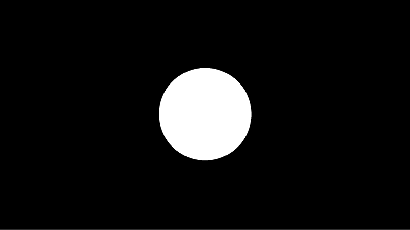
The circle SDF will give us a signed distance value equal to the distance from the center of the circle. Remember, a shader draws every pixel in parallel, and each pixel will be a certain distance away from the center of the circle.
Next, we can create a function that will add glow proportional to the distance away from the center of the circle. If you go to Desmos, then you can enter y = 1 / x to visualize the function we will be using. Let’s pretend that x represents the signed distance value for a circle. As it increases, the output, y, gets smaller or diminishes.
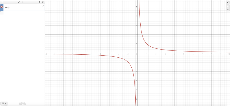
Let’s use this function to create glow in our code.
1void mainImage( out vec4 fragColor, in vec2 fragCoord )
2{
3 vec2 uv = fragCoord/iResolution.xy; // x: <0, 1>, y: <0, 1>
4 uv -= 0.5; // x: <-0.5, 0.5>, y: <-0.5, 0.5>
5 uv.x *= iResolution.x/iResolution.y; // x: <-0.5, 0.5> * aspect ratio, y: <-0.5, 0.5>
6
7 float d = length(uv) - 0.2; // signed distance function
8
9 vec3 col = vec3(step(0., -d)); // create white circle with black background
10
11 float glow = 0.01/d; // create glow and diminish it with distance
12 col += glow; // add glow
13
14 fragColor = vec4(col,1.0); // output color
15}When you run this code, you may see weird artifacts appear.
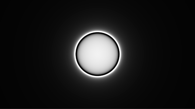
The y = 1/x function may result in unexpected values when x is less than or equal to zero. This can cause the compiler to perform weird calculations that cause unexpected colors. We can use the clamp function to make sure the glow value stays between zero and one.
1void mainImage( out vec4 fragColor, in vec2 fragCoord )
2{
3 vec2 uv = fragCoord/iResolution.xy; // x: <0, 1>, y: <0, 1>
4 uv -= 0.5; // x: <-0.5, 0.5>, y: <-0.5, 0.5>
5 uv.x *= iResolution.x/iResolution.y; // x: <-0.5, 0.5> * aspect ratio, y: <-0.5, 0.5>
6
7 float d = length(uv) - 0.2; // signed distance function
8
9 vec3 col = vec3(step(0., -d)); // create white circle with black background
10
11 float glow = 0.01/d; // create glow and diminish it with distance
12 glow = clamp(glow, 0., 1.); // remove artifacts
13 col += glow; // add glow
14
15 fragColor = vec4(col,1.0); // output color
16}When you run the code, you should see a glowing circle appear!
Increasing Glow Strength
You can multiply the glow by a value to make the circle appear even brighter and have the glow travel a larger distance.
1void mainImage( out vec4 fragColor, in vec2 fragCoord )
2{
3 vec2 uv = fragCoord/iResolution.xy; // x: <0, 1>, y: <0, 1>
4 uv -= 0.5; // x: <-0.5, 0.5>, y: <-0.5, 0.5>
5 uv.x *= iResolution.x/iResolution.y; // x: <-0.5, 0.5> * aspect ratio, y: <-0.5, 0.5>
6
7 float d = length(uv) - 0.2; // signed distance function
8
9 vec3 col = vec3(step(0., -d)); // create white circle with black background
10
11 float glow = 0.01/d; // create glow and diminish it with distance
12 glow = clamp(glow, 0., 1.); // remove artifacts
13
14 col += glow * 5.; // add glow
15
16 fragColor = vec4(col,1.0); // output color
17}
Glowing Star
We’ve been using circles, but we can make other shapes glow too! Let’s try using the sdStar5 SDF from Inigo Quilez’s 2D distance functions. You can learn more about how to use this SDF in Part 5 of my Shadertoy tutorial series.
1float sdStar5(vec2 p, float r, float rf)
2{
3 const vec2 k1 = vec2(0.809016994375, -0.587785252292);
4 const vec2 k2 = vec2(-k1.x,k1.y);
5 p.x = abs(p.x);
6 p -= 2.0*max(dot(k1,p),0.0)*k1;
7 p -= 2.0*max(dot(k2,p),0.0)*k2;
8 p.x = abs(p.x);
9 p.y -= r;
10 vec2 ba = rf*vec2(-k1.y,k1.x) - vec2(0,1);
11 float h = clamp( dot(p,ba)/dot(ba,ba), 0.0, r );
12
13 return length(p-ba*h) * sign(p.y*ba.x-p.x*ba.y);
14}
15
16void mainImage( out vec4 fragColor, in vec2 fragCoord )
17{
18 vec2 uv = fragCoord/iResolution.xy; // x: <0, 1>, y: <0, 1>
19 uv -= 0.5; // x: <-0.5, 0.5>, y: <-0.5, 0.5>
20 uv.x *= iResolution.x/iResolution.y; // x: <-0.5, 0.5> * aspect ratio, y: <-0.5, 0.5>
21
22 float d = sdStar5(uv, 0.12, 0.45); // signed distance function
23
24 vec3 col = vec3(step(0., -d));
25
26 col += clamp(vec3(0.001/d), 0., 1.) * 12.; // add glow
27
28 col *= vec3(1, 1, 0);
29
30 fragColor = vec4(col,1.0);
31}When you run the code, you should see a glowing star! 🌟

You can also add a rotate function, similar to what I discussed in Part 3 of my Shadertoy tutorial series, to make the star spin.
1vec2 rotate(vec2 uv, float th) {
2 return mat2(cos(th), sin(th), -sin(th), cos(th)) * uv;
3}
4
5float sdStar5(vec2 p, float r, float rf)
6{
7 const vec2 k1 = vec2(0.809016994375, -0.587785252292);
8 const vec2 k2 = vec2(-k1.x,k1.y);
9 p.x = abs(p.x);
10 p -= 2.0*max(dot(k1,p),0.0)*k1;
11 p -= 2.0*max(dot(k2,p),0.0)*k2;
12 p.x = abs(p.x);
13 p.y -= r;
14 vec2 ba = rf*vec2(-k1.y,k1.x) - vec2(0,1);
15 float h = clamp( dot(p,ba)/dot(ba,ba), 0.0, r );
16
17 return length(p-ba*h) * sign(p.y*ba.x-p.x*ba.y);
18}
19
20void mainImage( out vec4 fragColor, in vec2 fragCoord )
21{
22 vec2 uv = fragCoord/iResolution.xy; // x: <0, 1>, y: <0, 1>
23 uv -= 0.5; // x: <-0.5, 0.5>, y: <-0.5, 0.5>
24 uv.x *= iResolution.x/iResolution.y; // x: <-0.5, 0.5> * aspect ratio, y: <-0.5, 0.5>
25
26 float d = sdStar5(rotate(uv, iTime), 0.12, 0.45); // signed distance function
27
28 vec3 col = vec3(step(0., -d));
29
30 col += clamp(vec3(0.001/d), 0., 1.) * 12.; // add glow
31
32 col *= vec3(1, 1, 0);
33
34 fragColor = vec4(col,1.0);
35}
Conclusion
In this tutorial, we learned how to make 2D shapes glow in a shader using signed distance functions (SDFs). We applied contrast between the color of the shape and background color. We also created a smooth gradient around the edges of the shape. These two criteria led to a simulated glow effect in our shaders. If you’d like to learn more about Shadertoy, please check out my Part 1 of my Shadertoy tutorial series.