Where Do I Start? A Very Gentle Introduction to Computer Graphics Programming
Understanding How It Works!
If you are here, it’s probably because you want to learn computer graphics. Each reader may have a different reason for being here, but we are all driven by the same desire: to understand how it works! Scratchapixel was created to answer this particular question. Here you will learn how it works and about techniques used to develop computer graphics-generated images, from the simplest and most essential methods to the more complicated and less common ones. You may like video games, and you would like to know how it works and how they are made. You may have seen a Pixar film and wondered what’s the magic behind it. Whether you are at school, or university, already working in the industry (or retired), it is never a wrong time to be interested in these topics, to learn or improve your knowledge, and we always need a resource like Scratchapixel to find answers to these questions. That’s why we are here.
Scratchapixel is accessible to all. There are lessons for all levels. Of course, it requires a minimum of knowledge in programming. While we plan to write a quick introductory lesson on programming shortly, Scratchapixel’s mission is about something other than teaching programming and C++ mainly. However, while learning about implementing different techniques for producing 3D images, you will likely improve your programming skills and learn a few programming tricks in the process. Whether you consider yourself a beginner or an expert in programming, you will find all sorts of lessons adapted to your level here. Start simple, with basic programs, and progress from there.
A gentle note, though, before we proceed further: we do this work on volunteering grounds. We do this in our spare time and provide the content for free. The authors of the lessons are not necessarily native English speakers and writers. While we are experienced in the field, we didn’t claim we were the best nor the most educated persons to teach about these topics. We make mistakes; we can write something entirely wrong or (not) precisely accurate. That’s why the content of Scratchapixel is now open source. So that you can help fix our mistakes if/when you spot them. Not to make us look better than we are but to help the community access much better quality content. Our goal is not to improve our fame but to provide the community with the best possible educational resources (and that means accuracy).
A Gentle Introduction to Computer Graphics Programming
You want to learn Computer Graphics (CG). First, do you know what it is? In the second lesson of this section, you can find a definition of computer graphics and learn about how it generally works. You may have heard about terms such as modeling, geometry, animation, 3D, 2D, digital images, 3D viewport, real-time rendering, and compositing. The primary goal of this section is to clarify their meaning and, more importantly, how they relate to each other – providing you with a general understanding of the tools and processes involved in making Computer Generated Imagery (CGI).
Our world is three-dimensional. At least as far as we can experience it with our senses; in other words, everything around you has some length, width, and depth. A microscope can zoom into a grain of sand to observe its height, width, and depth. Some people also like to add the dimension of time. Time plays a vital role in CGI, but we will return to this later. Objects from the real world then are three-dimensional. That’s a fact we can all agree on without having to prove it (we invite curious readers to check the book by Donald Hoffman, “The Case Against Reality”, which challenges our conception of space-time and reality). What’s interesting is that vision, one of the senses by which this three-dimensional world can be experienced, is primarily a two-dimensional process. We could maybe say that the image created in our mind is dimensionless (we don’t understand yet very well how images ‘appear’ in our brain), but when we speak of an image, it generally means to us a flat surface, on which the dimensionality of objects has been reduced from three to two dimensions (the surface of the canvas or the surface of the screen). The only reason why this image on the canvas looks accurate to our brain is that objects get smaller as they get further away from where you stand, an effect called foreshortening. Think of an image as nothing more than a mirror reflection. The surface of the mirror is perfectly flat, and yet, we can’t make the difference between looking at the image of a scene reflected from a mirror and looking directly at the scene: you don’t perceive the reflection, just the object. It’s only because we have two eyes that we can see things in 3D, which we call stereoscopic vision. Each eye looks at the same scene from a slightly different angle, and the brain can use these two images of the same scene to approximate the distance and the position of objects in 3D space with respect to each other. However, stereoscopic vision is quite limited as we can’t measure the distance to objects or their size very accurately (which computers can do). Human vision is quite sophisticated and an impressive result of evolution, but it’s a trick and can be fooled easily (many magicians’ tricks are based on this). To some extent, computer graphics is a means by which we can create images of artificial worlds and present them to the brain (through the mean of vision), as an experience of reality (something we call photo-realism), exactly like a mirror reflection. This theme is quite common in science fiction, but technology is close to making this possible.
What have we learned so far? That the world is three-dimensional, that the way we look at it is two-dimensional, and that if you can replicate the shape and the appearance of objects, the brain can not make the difference between looking at these objects directly and looking at an image of these objects. Computer graphics are not limited to creating photoreal images. Still, while it’s easier to develop non-photo-realistic images than perfectly photo-realistic ones, the goal of computer graphics is realism (as much in the way things move than they appear).
All we need to do now is learn the rules for making such a photo-real image, and that’s what you will also learn here on Scratchapixel.
Describing Objects Populating the Virtual World
The difference between the painter who is painting a real scene (unless the subject of the painting comes from their imagination), and us, trying to create an image with a computer, is that we have first somehow to describe the shape (and the appearance) of objects making up the scene we want to render an image of to the computer.
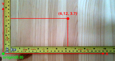
Figure 1: a 2D Cartesian coordinative system defined by its two axes (x and y) and the origin. This coordinate system can be used as a reference to define the position or coordinates of points within the plane.
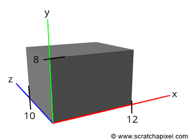
Figure 2: the size of the box and its position with respect to the world origin can be used to define the position of its corners.
One of the simplest and most important concepts we learn at school is the idea of space in which points can be defined. The position of a point is generally determined by an origin. This is typically the tick marked with the number zero on a ruler. If we use two rulers, one perpendicular to the other, we can define the position of points in two dimensions. Add a third ruler perpendicular to the first two, and you can determine the position of points in three dimensions. The actual numbers representing the position of the point with respect to one of the tree rulers are called the points coordinates. We are all familiar with the concept of coordinates to mark where we are with respect to some reference point or line (for example, the Greenwich meridian). We can now define points in three dimensions. Let’s imagine that you just bought a computer. This computer probably came in a box with eight corners (sorry for stating the obvious). One way of describing this box is to measure the distance of these 8 corners with respect to one of the corners. This corner acts as the origin of our coordinate system, and the distance of this reference corner with respect to itself will be 0 in all dimensions. However, the distance from the reference corner to the other seven corners will be different than 0. Let’s imagine that our box has the following dimensions:
corner 1: ( 0, 0,  0)
corner 2: (12, 0,  0)
corner 3: (12, 8,  0)
corner 4: ( 0, 8,  0)
corner 5: ( 0, 0, 10)
corner 6: (12, 0, 10)
corner 7: (12, 8, 10)
corner 8: ( 0, 8, 10)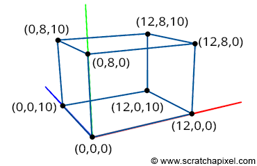
Figure 3: a box can be described by specifying the coordinates of its eight corners in a Cartesian coordinate system.
The first number represents the width, the second the height, and the third the corner’s depth. Corner 1, as you can see, is the origin from which all the corners have been measured. You need to write a program in which you will define the concept of a three-dimensional point and use it to store the coordinates of the eight points you just measured. In C/C++, such a program could look like this:
typedef float Point[3];
int main()
{
    Point corners[8] = {
        { 0, 0,  0},
        {12, 0,  0},
        {12, 8,  0},
        { 0, 8,  0},
        { 0, 0, 10},
        {12, 0, 10},
        {12, 8, 10},
        { 0, 8, 10},
    };

    return 0;
}
Like in any language, there are always different ways of doing the same thing. This program shows one possible way in C/C++ to define the concept of point (line 1) and store the box corners in memory (in this example, as an array of eight points).
You have created your first 3D program. It doesn’t produce an image yet, but you can already store the description of a 3D object in memory. In CG, the collection of these objects is called a scene (a scene also includes the concept of camera and lights, but we will talk about this another time). As suggested, we still need two essential things to make the process complete and interesting. First, to represent the box in the computer’s memory, ideally, we also need a system that defines how these eight points are connected to make up the faces of the box. In CG, this is called the topology of the object (an object is also called a model). We will talk about this in the lesson on Geometry and the 3D Rendering for Beginners section (in the lesson on rendering triangles and polygonal meshes). Topology refers to how points we call vertices are connected to form faces (or flat surfaces). These faces are also called polygons. The box would be made of six faces or six polygons, and the polygons form what we call a polygonal mesh or simply a mesh. The second thing we still need is a system to create an image of that box. This requires projecting the box’s corners onto an imaginary canvas, a process we call perspective projection.
Creating an Image of this Virtual World
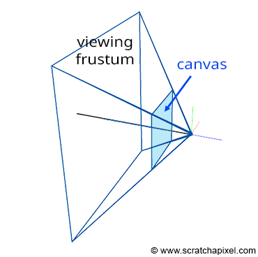
Figure 4: if you connect the corners of the canvas to the eye, which by default is aligned with our Cartesian coordinate system, and extend the lines further into the scene, you get some pyramid which we call a viewing frustum. Any object within the frustum (or overlapping it) is visible and will appear on the image.
Projecting a 3D point on the surface of the canvas involves a particular matrix called the perspective matrix (don’t worry if you don’t know what a matrix is). Using this matrix to project points is optional but makes things much more manageable. However, you don’t need mathematics and matrices to figure out how it works. You can see an image or a canvas as some flat surface is placed away from the eye. Trace four lines, all starting from the eye to each one of the four corners of the canvas, and extend these lines further away into the world (as far as you can see). You get a pyramid which we call a viewing frustum (and not frustrum). The viewing frustum defines some volume in 3D space, and the canvas is just a plane cutting of this volume perpendicular to the eye’s line of sight. Place your box in front of the canvas. Next, trace a line from each corner of the box to the eye and mark a dot where the line intersects the canvas. Find the dots on the canvas corresponding to each of the twelve edges of the box, and trace a line between these dots. What do you see? An image of the box.
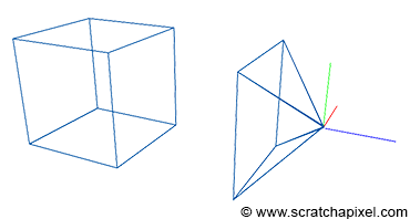
Figure 5: the box is moved in front of our camera setup. The coordinates of the box corners are expressed with respect to this Cartesian coordinate system.
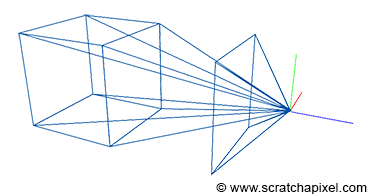
Figure 6: connecting the box corners to the eye.
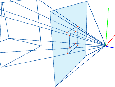
Figure 7: the intersection points between these lines and the canvas are the projection of the box corners onto the canvas. Connecting these points creates a wireframe image of the box.
The three rulers used to measure the coordinates of the box corner form what we call a coordinate system. It’s a system in which points can be measured to. All points’ coordinates relate to this coordinate system. Note that a coordinate can either be positive or negative (or zero) depending on whether it’s located on the right or the left of the ruler’s origin (the value 0). In CG, this coordinate system is often called the world coordinate system, and the point (0,0,0) is the origin.
Let’s move the apex of the viewing frustum at the origin and orient the line of sight (the view direction) along the negative z-axis (Figure 3). Many graphics applications use this configuration as their default “viewing system”. Remember that the top of the pyramid is the point from which we will look at the scene. Let’s also move the canvas one unit away from the origin. Finally, let’s move the box some distance from the origin, so it is fully contained within the frustum’s volume. Because the box is in a new position (we moved it), the coordinates of its eight corners changed, and we need to measure them again. Note that because the box is on the left side of the ruler’s origin from which we measure the object’s depth, all depth coordinates, also called z-coordinates, will be negative. Four corners are below the reference point used to measure the object’s height and will have a negative height or y-coordinate. Finally, four corners will be to the left of the ruler’s origin, measuring the object’s width: their width or x-coordinates will also be negative. The new coordinates of the box’s corners are:
corner 1: ( 1, -1, -5)
corner 2: ( 1, -1, -3)
corner 3: ( 1,  1, -5)
corner 4: ( 1,  1, -3)
corner 5: (-1, -1, -5)
corner 6: (-1, -1, -3)
corner 7: (-1,  1, -5)
corner 8: (-1,  1, -3)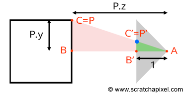
Figure 8: the coordinates of the point P’, the projection of P on the canvas can be computed using simple geometry. The rectangle ABC and AB’C’ are said to be similar.
Let’s look at our setup from the side and trace a line from one of the corners to the origin (the viewpoint). We can define two triangles: ABC and AB’C’. As you can see, these two triangles have the same origin (A). They are also somehow copies of each other in that the angle defined by the edges AB and AC is the same as the angle determined by the edge AB’, AC’. Such triangles are said to be similar triangles in mathematics. Similar triangles have an interesting property: the ratio between their adjacent and opposite sides is the same. In other words:
$$ {BC \over AB} = {B'C' \over AB'}. $$Because the canvas is 1 unit away from the origin, we know that AB’ equals 1. We also know the position of B and C, which are the corner’s z (depth) and y coordinates (height), respectively. If we substitute these numbers in the above equation, we get:
$$ {P.y \over P.z} = {P'.y \over 1}. $$Where y’ is the y coordinate of the point where the line going from the corner to the viewpoint intersects the canvas, which is, as we said earlier, the dot from which we can draw an image of the box on the canvas. Thus:
$$ P'.y = {P.y \over P.z}. $$As you can see, the projection of the corner’s y-coordinate on the canvas is nothing more than the corner’s y-coordinate divided by its depth (the z-coordinate). This is one of computer graphics’ most straightforward and fundamental relations, known as the z or perspective divide. The same principle applies to the x coordinate. The projected point x coordinate (x’) is the corner’s x coordinate divided by its z coordinate.
Note, though, that because the z-coordinate of P is negative in our example (we will explain why this is always the case in the lesson from the Foundations of 3D Rendering section dedicated to the perspective projection matrix) when the x-coordinate is positive, the projected point’s x-coordinate will become negative (similarly, if P.x is negative, P’.x will become positive. The same problem happens with the y-coordinate). As a result, the image of the 3D object is mirrored both vertically and horizontally, which is different from the effect we want. Thus, to avoid this problem, we will divide the P.x and P.y coordinates with -P.z instead, preserving the sign of the x and y coordinates. We finally get:
$$ \begin{array}{l} P'.x = {P.x \over -P.z}\\ P'.y = {P.y \over -P.z}. \end{array} $$We now have a method to compute the actual positions of the corners as they appear on the surface of the canvas. These are the two-dimensional coordinates of the points projected on the canvas. Let’s update our basic program to compute these coordinates:
typedef float Point[3];
int main()
{
    Point corners[8] = {
         { 1, -1, -5},
         { 1, -1, -3},
         { 1,  1, -5},
         { 1,  1, -3},
         {-1, -1, -5},
         {-1, -1, -3},
         {-1,  1, -5},
         {-1,  1, -3}
    };

    for (int i = 0; i < 8; ++i) {
        // divide the x and y coordinates by the z coordinate to
        // project the point on the canvas
        float x_proj = corners[i][0] / -corners[i][2];
        float y_proj = corners[i][1] / -corners[i][2];
        printf("projected corner: %d x:%f y:%f\n", i, x_proj, y_proj);
    }

    return 0;
}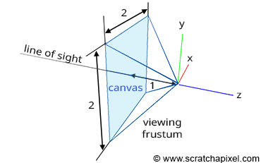
Figure 9: in this example, the canvas is 2 units along the x-axis and 2 units along the y-axis. You can change the dimension of the canvas if you wish. By making it bigger or smaller, you will see more or less of the scene.
The size of the canvas itself is also arbitrary. It can also be a square or a rectangle. In our example, we made it two units wide in both dimensions, which means that the x and y coordinates of any points lying on the canvas are contained in the range -1 to 1 (Figure 9).
Question: what happens if any of the projected point coordinates is not in this range if, for > instance, x' equals -1.1?
The point is not visible; it lies outside the boundary of the canvas.
At this point, we say that the projected point coordinates are in screen space (the space of the screen, where screen and canvas in this context our synonymous). But they are not easy to manipulate because they can either be negative or positive, and we need to know what they refer to with respect to, for example, the dimension of your computer screen (if we want to display these dots on the screen). For this reason, we will first normalize them, which means we convert them from whatever range they were initially into the range [0,1]. In our case, because we need to map the coordinates from -1,1 to 0,1, we can write:
float x_proj_remap = (1 + x_proj) / 2;
float y_proj_remap = (1 + y_proj) / 2;
The coordinates of the projected points are now in the range of 0,1. Such coordinates are said to be defined in NDC space, which stands for Normalized Device Coordinates. This is convenient because regardless of the original size of the canvas (or screen), which can be different depending on the settings you used, we now have all points’ coordinates defined in a common space. The term normalize is ubiquitous. You somehow remap values from whatever range they were initially into the range [0,1]. Finally, we generally define point coordinates with regard to the dimensions of the final image, which, as you may know, or not, is defined in terms of pixels. A digital image is nothing else than a two-dimensional array of pixels (as is your computer screen).
A 512x512 image is a digital image having 512 rows of 512 pixels; if you prefer to see it the other way around, 512 columns of 512 vertically aligned pixels. Since our coordinates are already normalized, all we need to do to express them in terms of pixels is to multiply these NDC coordinates by the image dimension (512). Here, our canvas being square, we will also use a square image:
#include <cstdlib>
#include <cstdio>

typedef float Point[3];

int main()
{
    Point corners[8] = {
         { 1, -1, -5},
         { 1, -1, -3},
         { 1,  1, -5},
         { 1,  1, -3},
         {-1, -1, -5},
         {-1, -1, -3},
         {-1,  1, -5},
         {-1,  1, -3}
    };

    const unsigned int image_width = 512, image_height = 512;

    for (int i = 0; i < 8; ++i) {
        // divide the x and y coordinates by the z coordinate to
        // project the point on the canvas
        float x_proj = corners[i][0] / -corners[i][2];
        float y_proj = corners[i][1] / -corners[i][2];
        float x_proj_remap = (1 + x_proj) / 2;
        float y_proj_remap = (1 + y_proj) / 2;
        float x_proj_pix = x_proj_remap * image_width;
        float y_proj_pix = y_proj_remap * image_height;
        printf("corner: %d x:%f y:%f\n", i, x_proj_pix, y_proj_pix);
    }

    return 0;
}
The resulting coordinates are said to be in raster space (XX, what does raster mean, please explain). Our program is still limited because it doesn’t create an image of the box, but if you compile it and run it with the following commands (copy/paste the code in a file and save it as box.cpp):
c++ box.cpp
./a.out
corner: 0 x:307.200012 y:204.800003
corner: 1 x:341.333344 y:170.666656
corner: 2 x:307.200012 y:307.200012
corner: 3 x:341.333344 y:341.333344
corner: 4 x:204.800003 y:204.800003
corner: 5 x:170.666656 y:170.666656
corner: 6 x:204.800003 y:307.200012
corner: 7 x:170.666656 y:341.333344</div>
You can use a paint program to create an image (set its size to 512x512) and add dots at the pixel coordinates you computed with the program. Then connect the dots to form the edges of the box, and you will get an actual image of the box (as shown in the video below). Pixel coordinates are integers, so you will need to round off the numbers given by the program.
What Have We Learned?
-
We first need to describe three-dimensional objects using things such as vertices and topology (information about how these vertices are connected to form polygons or faces) before we can produce an image of the 3D scene (a scene is a collection of objects).
-
That rendering is the process by which an image of a 3D scene is created. No matter which technique you use to create 3D models (there are quite a few), rendering is a necessary step to ‘see’ any 3D virtual world.
-
From this simple exercise, it is apparent that mathematics (more than programming) is essential in making an image with a computer. A computer is merely a tool to speed up the computation, but the rules used to create this image are pure mathematics. Geometry plays a vital role in this process, mainly to handle objects’ transformations (scale, rotation, translation) but also provide solutions to problems such as computing angles between lines or finding out the intersection between a line and other simple shapes (a plane, a sphere, etc.).
-
In conclusion, computer graphics is mostly mathematics applied to a computer program whose purpose is to generate an image (photo-real or not) at the quickest possible speed (and the accuracy that computers are capable of).
-
Modeling includes all techniques used to create 3D models. Modeling techniques will be discussed in the Geometry/Modeling section.
-
While static models are acceptable, it is also possible to animate them over time. This means that an image of the model at each time step needs to be rendered (you can translate, rotate or scale the box a little between each consecutive image by animating the corners’ coordinates or applying a transformation matrix to the model). More advanced animation techniques can be used to simulate the deformation of the skin by bones and muscles. But all these techniques share that geometry (the faces making up the models) is deformed over time. Hence, as the introduction suggests, time is also essential in CGI. Check the Animation section to learn about this topic.
-
One particular field overlaps both animation and modeling. It includes all techniques used to simulate the motion of objects in a realistic manner. A vast area of computer graphics is devoted to simulating the motion of fluids (water, fire, smoke), fabric, hair, etc. The laws of physics are applied to 3D models to make them move, deform or break like they would in the real world. Physics simulations are generally very computationally expensive, but they can also run in real-time (depending on the scene’s complexity you simulate).
-
Rendering is also a computationally expensive task. How expensive depends on how much geometry your scene is made up of and how photo-real you want the final image to be. In rendering, we differentiate two modes, an offline and a real-time rendering mode. Real-time is used (it’s a requirement) for video games, in which the content of the 3D scenes needs to be rendered at least 30 frames per second (generally, 60 frames a second is considered a standard). The GPU is a processor specially designed to render 3D scenes at the quickest possible speed. Offline rendering is commonly used in producing CGI for films where real-time is not required (images are precomputed and stored before being displayed at 24 or 30, or 60 fps). It may take a few seconds to hours before one single image is complete. Still, it handles far more geometry and produces higher-quality images than real-time rendering. However, real-time or offline rendering tends to overlap more these days, with video games pushing the amount of geometry they can handle and quality and offline rendering engines trying to take advantage of the latest advancements in the field of CPU technology to improve their performances significantly.
Well, we/you learned a lot!
Where Should I Start?
We hope the simple box example got you hooked, but this introduction’s primary goal is to underline geometry’s role in computer graphics. Of course, it’s not only about geometry, but many problems can be solved with geometry. Most computer graphics books start with a chapter on geometry, which is always a bit discouraging because you need to study a lot before you can get to making fun stuff. However, we recommend you read the lesson on Geometry before anything else. We will talk and learn about points, vectors, and normals. We will learn about coordinate systems and, more importantly, about matrices. Matrices are used extensively to handle rotation, scaling, and/or translation; generally, to handle transformations. These concepts are used everywhere throughout all computer graphics literature, so you must study them first.
Many (most?) CG books provide a poor introduction to geometry may be because the authors assume that readers already know about it or that it’s better to read books devoted to this particular topic. Our lesson on geometry is different. It’s extensive, relevant to your daily production work, and explains everything using simple words. We strongly recommend you start your journey into computer graphics programming by reading this lesson first.
What Should I Read Next?
Learning computer graphics programming with rendering is generally more accessible and more fun. That beginners section was written for people who are entirely new to computer graphics programming. So keep reading the lesson from this section in chronological order if your goal is to proceed further.